
Boiler and chiller plants supply the thermal utilities that most industrial processes depend on: steam for heating, drying, and sterilization, and chilled water for cooling and HVAC. Because these plants run continuously and consume significant fuel and electricity, their automation directly affects energy cost, reliability, and uptime. This article covers the control loops, the sequencing logic, and the efficiency practices for automated boiler and chiller plants.
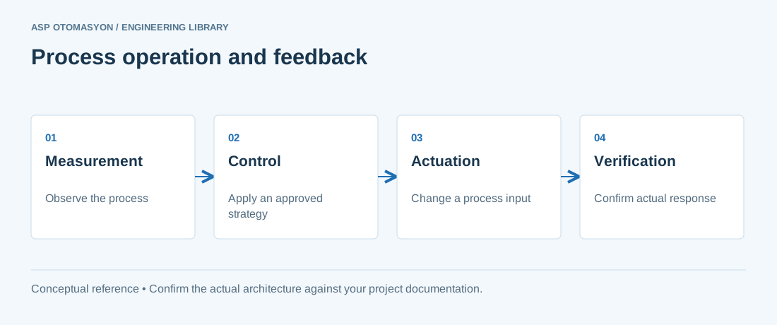
Boiler Control Fundamentals
Steam pressure control
The master loop maintains header steam pressure by adjusting fuel input (and combustion air). When steam demand rises, pressure drops and the controller increases firing rate. The firing rate is limited by the boiler's maximum rating and by safety interlocks.
Combustion control (air–fuel ratio)
For safe and efficient firing, fuel and air must be matched: too little air produces CO and soot (and risk of explosion), too much air wastes energy heating excess air. Modern systems use cross-limiting control:
- On load increase, air is increased first, then fuel follows (air leads).
- On load decrease, fuel is reduced first, then air follows (fuel leads).
This prevents a fuel-rich condition during transients. Oxygen (O₂) trim using a flue-gas O₂ analyzer fine-tunes the ratio continuously.
Drum level control (steam boilers)
Maintaining drum level is safety-critical. Control strategies:
- Single element: level-only control; adequate for small, stable boilers.
- Two element: level + steam flow (feedforward on demand).
- Three element: level + steam flow + feedwater flow; the standard for medium and large boilers — it corrects for shrink/swell and maintains a tight mass balance.
Low-low and high-high drum level trips are mandatory safety interlocks; the feedwater control system must never be the only protection.
Boiler Automation Architecture
Steam header pressure
        │
        ▼
Boiler master (firing demand)
   ├──► Combustion control (air/fuel cross-limited, O2 trim)
   ├──► Drum level control (3-element)
   └──► Burner management system (BMS, safety: purge, flame, trips)
- Burner management system (BMS): a dedicated, safety-certified system that manages light-off sequence, flame supervision, and trip conditions. It is separate from the modulating control loops.
- Interlocks: low water level, loss of flame, high steam pressure, fuel gas pressure anomalies — all trip the boiler to a safe state.
- Multiple boilers: a boiler master sequences multiple units: run the minimum number at high efficiency, add boilers as demand grows, and rotate lead units for even wear.
Chiller Plant Control Fundamentals
Chilled water supply temperature
The primary loop keeps the chilled water supply temperature at setpoint by modulating chiller capacity (via the chiller's own controls). Reset the supply setpoint upward when loads allow (e.g., at night or in mild weather) — every degree of reset saves compressor energy.
Condenser water optimization
Cooling tower fans and condenser water pumps are significant energy users. Optimize:
- Run the minimum number of fans needed; stage fans on condenser water temperature.
- Reset condenser water setpoint to a "floating" value that minimizes total plant power (compressor + fans + pumps), typically near the wet-bulb limit.
- Use variable-speed pumps instead of constant-flow designs where retrofits allow.
Chiller sequencing
Multiple chillers are sequenced to match cooling load:
- Start/stop chillers based on load and efficiency curves (part-load efficiency varies by chiller type).
- Equalize run hours and avoid short-cycling.
- Integrate thermal storage (ice or water) where the tariff makes off-peak chilling economic.
Efficiency Practices
- Measure specific energy: track steam per tonne of product and kWh per ton-hour of cooling; trend against production (see the energy monitoring and historian articles).
- Recover heat: boiler blowdown heat recovery, economizers on flue gas, and chiller condenser heat reuse for preheating.
- Maintain combustion efficiency: O₂ trim, burner maintenance, and soot blowing keep the boiler near its design efficiency.
- Reduce steam pressure where possible: lower header pressure reduces losses and leak rates; verify process requirements first.
- Steam trap maintenance: failed traps waste steam continuously (see the utility optimization discipline applied to steam).
- Night/weekend setbacks: reduce supply temperatures and shut down unused utilities during idle periods.
Automation and Integration
- SCADA integration: boiler and chiller plants feed the site SCADA/historian: pressures, temperatures, flows, equipment status, and efficiency KPIs.
- Alarm management: apply the alarm philosophy (see alarm rationalization) — utility alarms must be meaningful, not constant chatter.
- Redundancy and testing: the BMS and critical interlocks need the same rigor as safety systems; test trips during planned outages.
- Energy tie-in: connect to the site's ISO 50001 EnMS and demand response capability: utilities are usually the first loads considered for shedding.
Common Pitfalls
- Undersized or oversized boilers/chillers — operating far from design load kills efficiency; consider multiple units sized to the load profile.
- Constant-speed pumps running 24/7 — one of the largest avoidable energy losses in utility plants.
- Bypassed interlocks — "temporary" bypasses of boiler trips are how serious accidents happen; enforce strict control.
- No performance monitoring — efficiency drifts quietly; trend data is the only way to see it.
- Neglecting water treatment — scale and corrosion degrade boiler and chiller performance and shorten life; water chemistry is part of the automation scope (monitoring, blowdown control).
Summary
Boiler and chiller automation combines safety-critical control (BMS, interlocks, three-element drum level) with efficiency-focused optimization (combustion trim, condenser water optimization, sequencing). Measure and trend the utility performance, maintain the safety interlocks rigorously, and integrate with the site's energy management and monitoring systems. The result is reliable thermal supply at the lowest achievable cost.
Apply this to your project
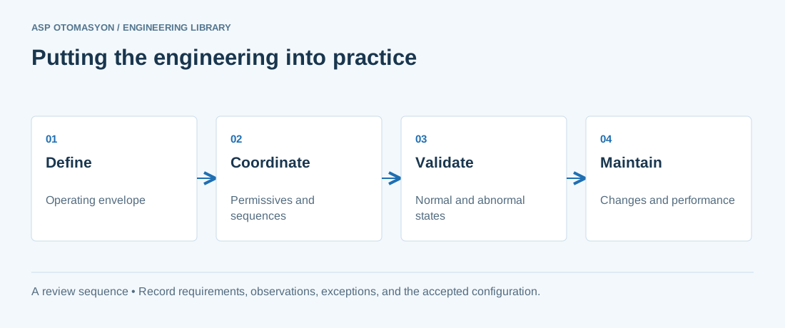
- Record process boundaries, required operating states, and interactions with independent protective systems.
- Check instrument quality, control authority, permissives, and operator responsibilities during state changes.
- Agree how tests, deviations, and configuration changes will be recorded within the facility's engineering procedures.
Follow an ASP project guide to connect the fundamentals with implementation and acceptance.
Primary references and further reading
Use the original specifications and product documentation for implementation details. The examples in this guide are illustrative engineering scenarios, not published project results.