
Pipeline automation is critical for the safe and efficient transport of oil, gas, and refined products. Modern pipeline SCADA systems integrate remote terminal units (RTUs), flow computers, and leak detection algorithms to provide real-time monitoring and control over hundreds or thousands of kilometers.
Remote Terminal Unit (RTU) Selection Criteria
Selecting the right RTU is one of the most consequential decisions in pipeline automation. Key selection criteria include:
- Environmental ratings — Pipeline RTUs are typically deployed in hazardous areas requiring Class I, Division 2 (or Zone 2 ATEX/IECEx) certification. The RTU enclosure must be rated for the temperature range of the installation region (−40°C to +60°C is common), with ingress protection of at least IP66 for direct outdoor exposure.
- Communication options — Pipeline RTUs must support multiple wide-area communication methods depending on terrain and infrastructure availability: satellite (VSAT, Iridium) for remote desert or mountain sections, cellular (4G LTE / 5G) for areas with mobile coverage, licensed or unlicensed radio (UHF, spread spectrum) for line-of-sight links, and fibre optic where trench communication is installed. Most modern RTUs support primary/backup communication path failover automatically.
- Power consumption — Remote pipeline stations often rely on solar panels with battery banks or thermoelectric generators. RTU power consumption must be minimised — typically 1–5 W in sleep mode, 5–15 W active. The RTU should support configurable duty cycling (e.g., transmit every 1–60 seconds) to conserve power.
- I/O requirements — Pipeline stations typically require: analogue inputs (4–20 mA) for pressure, temperature, and flow; digital inputs for valve limit switches and status contacts; digital outputs for valve control solenoids; pulse inputs for flow meter totalisers; and serial/Ethernet ports for flow computers and other intelligent devices.
RTU Deployment and Configuration
RTUs are deployed at each valve station, pig launcher/receiver, meter station, and intermediate block valve along the pipeline. Typical spacing is 20–50 km depending on terrain and regulatory requirements. Each RTU performs local control functions — including automatic valve closure on high/low pressure detection — independent of SCADA master communications, ensuring safe operation even during communication outages. Modern RTUs support IEC 61131-3 programming (ladder logic, structured text) for local control logic, and DNP3 or IEC 60870-5-101/104 protocols for SCADA communication. Remote diagnostics capability — firmware upgrades, configuration changes, and troubleshooting — is essential to avoid costly site visits.
Computational Pipeline Monitoring (CPM) per API 1130
API 1130, "Computational Pipeline Monitoring Systems," defines the framework for software-based leak detection. The three most widely deployed CPM methods are:
Mass Balance (Conservation of Mass)
The mass balance method continuously compares the total mass flow entering the pipeline with the total mass flow leaving, accounting for changes in pipeline inventory (packing/unpacking effects). Mathematically:
ΔM = Min − Mout − ΔMpack
If ΔM exceeds a calculated threshold (accounting for measurement uncertainty) for a sustained period, a leak alarm is generated. Mass balance is simple, inexpensive, and effective for large leaks (≥5% of flow), but less sensitive to small leaks and limited by flow meter accuracy (typically ±0.15% to ±0.5% on each meter, yielding a detection threshold of approximately ±1–3% of flow). Meter proving and temperature/pressure compensation are essential to minimise false alarms.
Negative Pressure Wave (NPW) Detection
When a pipeline rupture or leak occurs, a sudden drop in pressure generates a rarefaction wave that travels in both directions from the leak point at the speed of sound in the fluid (approximately 1000–1400 m/s for liquid hydrocarbons). Pressure transmitters installed at each station (sampling at 50–100 Hz) detect the wave arrival time. By correlating arrival times at two or more stations, the leak location can be calculated:
Distance = ((t2 − t1) × vs + L) / 2
where t1 and t2 are wave arrival times at upstream and downstream stations, vs is the wave speed, and L is the distance between stations. NPW can detect leaks as small as 1–2% of flow within seconds, making it the fastest method, but it requires high-speed sampling and is sensitive to pressure noise from pump start/stop and valve operations.
Real-Time Transient Model (RTTM)
RTTM is the most sophisticated CPM method. It solves the full set of one-dimensional fluid dynamic equations (continuity, momentum, and energy) in real-time using boundary conditions from field measurements (inlet pressure, outlet pressure, flow rate, temperature). The RTTM predicts the expected pressure and flow profiles along the pipeline and compares them with actual measurements. Deviations beyond a calculated threshold indicate a potential leak. RTTM can detect leaks as small as 0.5–1% of flow, provides accurate location estimation, and adapts to changing pipeline conditions (product switching, batch tracking). The trade-off is computational complexity, requiring robust RTU or server hardware and detailed pipeline geometry data (elevation profile, diameter, wall roughness).
Leak Detection Performance Metrics
API 1130 and regulatory bodies (PHMSA in the US, EIGA in Europe) define several key performance metrics for leak detection systems:
- Detection threshold — The minimum leak rate (as a percentage of nominal flow or absolute volume per hour) that the system can reliably detect. Typical targets: 1–2% of maximum flow rate for liquid pipelines, 0.5–1% for gas pipelines.
- Location accuracy — How precisely the system can estimate the leak position. NPW and RTTM can achieve location accuracy within ±100–500 metres under favourable conditions, enabling crews to be dispatched directly to the leak site.
- Detection time — The elapsed time between leak onset and system alarm. NPW: seconds to minutes; RTTM: minutes; mass balance: minutes to hours depending on leak size and packing compensation.
- False alarm rate — Every false alarm erodes operator trust and may lead to alarm suppression or ignored alarms. Modern systems use signal validation, voting logic, and adaptive thresholds to keep false alarms below one per month per pipeline.
Emergency Shutdown (ESD) System per IEC 61511
Pipeline ESD systems are safety-instrumented functions (SIFs) designed and validated per IEC 61511 (functional safety for the process industry). Key design aspects:
- SIL determination — Each ESD function (e.g., "Close Block Valve on High Pressure" or "Isolate Section on Leak Confirmation") receives a Safety Integrity Level (SIL) rating (typically SIL 2 or SIL 3) based on a Layer of Protection Analysis (LOPA).
- Valve closure logic — Emergency shutdown valves (ESDVs) are typically spring-return, fail-closed (for liquid lines) or fail-open (for gas lines with blowdown). The RTU or safety PLC initiates closure by de-energising the solenoid pilot valve. Closure time is calculated to avoid pressure surge (water hammer) while still isolating the leak rapidly — typically 30–120 seconds per valve.
- Voting architecture — To balance safety and availability, ESD sensors use 2oo3 (two-out-of-three) or 1oo2D voting. For example, three pressure transmitters at each station with a 2oo3 vote: if any two agree on high pressure, the shutdown is initiated.
- Proof testing — ESD valves and sensors must be proof-tested at defined intervals (typically 1–3 years) to verify they can still perform their safety function. Partial stroke testing of valves extends the interval by demonstrating valve movement without full closure.
Pipeline SCADA Architecture
A typical pipeline SCADA system is arranged in a hierarchical topology:
- Master Station (Primary) — The central control room with dual-redundant SCADA servers, operator workstations, and a large-screen display wall. The master station polls all RTUs cyclically (typical poll interval: 1–10 seconds), processes alarms, performs leak detection calculations, and provides the human-machine interface for pipeline operators.
- Backup Master Station — A geographically separate facility with identical hardware and software that mirrors the primary. In the event of a primary station failure, control is transferred to the backup with minimal interruption. Automatic failover is tested periodically.
- Data Concentration — In large pipeline networks, data concentrators at regional hubs collect RTU data via radio or cellular and forward it to the master station over a high-bandwidth link (fibre or satellite). This reduces polling burden on the master station and provides local alarm processing.
- Communications Network — A mix of private radio, cellular (with VPN), VSAT satellite, and fibre optic links, configured with automatic failover. The network must support the bandwidth required for CPM data (high-speed pressure samples for NPW, full SCADA data for RTTM).
- Cybersecurity per IEC 62443 — Pipeline SCADA is critical infrastructure. Defence-in-depth measures include: firewalls between IT and OT networks, DMZ for data historians and application servers, role-based access control, intrusion detection systems (IDS), and encrypted communications (TLS for TCP, AES-256 for radio). NERC CIP requirements apply for electrically-driven pumping stations.
ASP OTOMASYON A.Ş. and its subsidiaries OPCTurkey and ASP Dijital provide end-to-end industrial engineering solutions for process automation, data operations and AI.
References & Further Reading
- API Standards — American Petroleum Institute — Official API standards covering pipeline design, SCADA requirements, leak detection, and operational safety for oil and gas pipeline systems.
- API 1130 — Computational Pipeline Monitoring (CPM) Systems — API recommended practice for computational pipeline monitoring systems used in leak detection and operational surveillance.
- ISO 13623 — Petroleum and Natural Gas Industries — Pipeline Transportation Systems — International standard for pipeline design, materials, construction, testing, and operational safety for hydrocarbon transport systems.
- IEC 62443 — Industrial Communication Network and System Security for Pipeline SCADA — International standard series for securing pipeline SCADA systems and RTU communication networks against cyber threats.
- NERC CIP — Critical Infrastructure Protection for Pipeline Control Systems — NERC standards for cybersecurity of bulk electric system assets, applicable to electrically driven pipeline pumping stations and control centres.
Apply this to your project
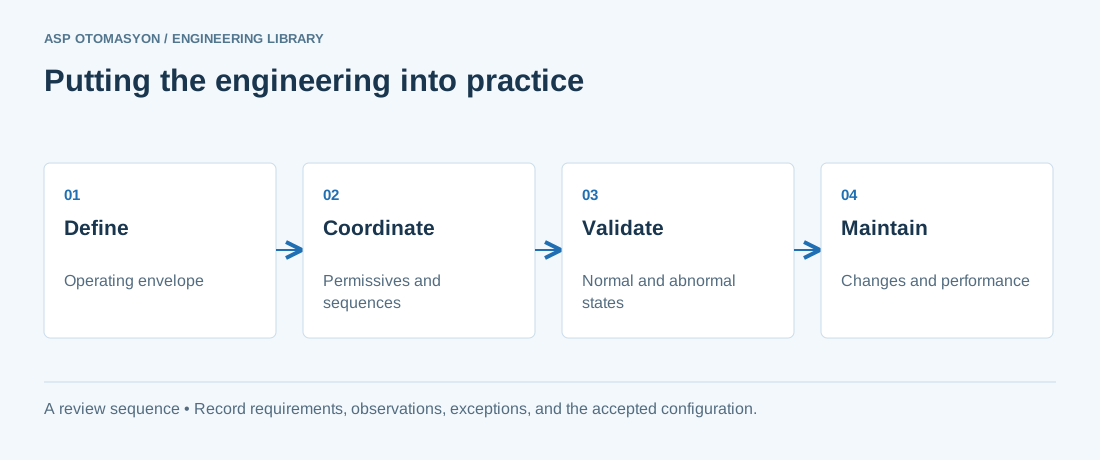
- Record process boundaries, required operating states, and interactions with independent protective systems.
- Check instrument quality, control authority, permissives, and operator responsibilities during state changes.
- Agree how tests, deviations, and configuration changes will be recorded within the facility's engineering procedures.
Follow an ASP project guide to connect the fundamentals with implementation and acceptance.
Primary references and further reading
Use the original specifications and product documentation for implementation details. The examples in this guide are illustrative engineering scenarios, not published project results.