
A Safety Instrumented System (SIS) is an independent layer of protection designed to bring a process to a safe state when predetermined conditions are violated. Unlike the basic process control system (BPCS), which handles normal operation, the SIS exists solely to prevent or mitigate hazardous events. In process industries — oil and gas, chemical, pharmaceutical, and power generation — SIS implementation is governed by IEC 61511, the international standard for functional safety in the process sector.
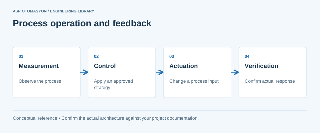
Safety Lifecycle per IEC 61511
IEC 61511 defines a comprehensive safety lifecycle that spans the entire existence of a SIS, from initial hazard analysis through decommissioning:
- Hazard and risk assessment — Identify hazardous events and evaluate risk without the SIS (unmitigated risk).
- Safety requirement allocation — Determine which risks are reduced by SIS vs. other layers (mechanical relief, physical containment).
- Safety requirements specification (SRS) — Define each Safety Instrumented Function (SIF), its SIL target, response time, and fail-safe state.
- Design and engineering — Select sensors, logic solvers, and final elements. Perform SIL verification calculations.
- Installation, commissioning, and validation — Install equipment, test against SRS, and validate that the achieved SIL meets the target.
- Operation and maintenance — Execute proof tests at defined intervals. Monitor demand rates and failure rates.
- Modification — Manage changes through a Management of Change (MOC) process.
- Decommissioning — Formal removal with risk assessment.
Safety Integrity Levels (SIL)
Each Safety Instrumented Function is assigned a SIL level based on the amount of risk reduction required. SIL is quantified using two metrics depending on the operating mode of the SIF:
| SIL | PFD (Low Demand) | PFH (High Demand / Continuous) | Risk Reduction Factor (RRF) |
|---|---|---|---|
| 1 | 0.1 – 0.01 | 10−5 – 10−6 per hour | 10 – 100 |
| 2 | 0.01 – 0.001 | 10−6 – 10−7 per hour | 100 – 1,000 |
| 3 | 0.001 – 0.0001 | 10−7 – 10−8 per hour | 1,000 – 10,000 |
| 4 | 0.0001 – 0.00001 | 10−8 – 10−9 per hour | 10,000 – 100,000 |
PFD (Probability of Failure on Demand) applies to SIFs that operate in low-demand mode (demanded less than once per year). PFH (Probability of Dangerous Failure per Hour) applies to high-demand or continuous mode SIFs.
SIL Verification
Achieving a target SIL requires meeting requirements in two categories defined by IEC 61508 (the parent standard):
- Hardware safety integrity — Based on probabilistic analysis. The calculated PFD or PFH must fall within the target SIL range. Key factors include dangerous failure rates (λD), diagnostic coverage (DC), safe failure fraction (SFF), proof test interval, and diagnostic test interval.
- Systematic safety integrity — Based on the quality of the development process. Achieved through rigorous design procedures, competence of personnel, verification and validation, and functional safety management (FSM).
Redundancy Architectures
SIS design uses redundancy to achieve the required hardware fault tolerance (HFT):
| Architecture | Description | HFT | Typical SIL Range |
|---|---|---|---|
| 1oo1 (1 out of 1) | Single channel — one component failure causes loss of function. | 0 | SIL 1–2 (with high SFF) |
| 1oo2 (1 out of 2) | Two channels — one operating, one standby. A single dangerous failure does not prevent the SIF. | 1 | SIL 2–3 |
| 2oo2 (2 out of 2) | Two channels — both must act. Increases safety but reduces availability (spurious trips increase). | 0 | SIL 2–3 |
| 2oo3 (2 out of 3) | Three channels — any two of three must agree. Balances safety and availability. Common for voting sensor arrays. | 1 | SIL 3–4 |
SIS vs. BPCS Separation
A fundamental principle of IEC 61511 is the independence of the SIS from the basic process control system. The SIS must be capable of bringing the process to a safe state regardless of any fault in the BPCS. This means:
- Separate sensors (or at least separate process connections and impulse lines).
- Separate logic solver (dedicated safety PLC, not shared with the DCS/PLC).
- Separate final elements (dedicated shutdown valves, separate from control valves).
- Separate engineering tools and access control.
Proof Testing
Proof testing is a critical maintenance activity that verifies the correct operation of the entire SIF — from sensor through logic solver to final element. The proof test interval directly impacts the calculated PFD:
- Full proof test — Simulates the process variable to verify the SIF responds correctly at the specified setpoint within the required response time.
- Partial stroke testing (PST) — For shutdown valves, periodically moves the valve a small percentage (typically 10–20%) to verify mechanical operation without fully shutting down the process. Extends the required full proof test interval.
- Interval — Determined during SIL verification. Typical intervals range from 6 months to 5 years depending on the target SIL and component failure rates.
ASP OTOMASYON provides full SIS engineering services — from hazard and operability (HAZOP) studies and SIL verification calculations through design, implementation, and lifecycle management per IEC 61511.
Apply this to your project
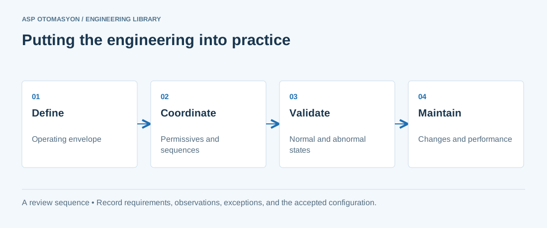
- Record process boundaries, required operating states, and interactions with independent protective systems.
- Check instrument quality, control authority, permissives, and operator responsibilities during state changes.
- Agree how tests, deviations, and configuration changes will be recorded within the facility's engineering procedures.
Follow an ASP project guide to connect the fundamentals with implementation and acceptance.
Primary references and further reading
Use the original specifications and product documentation for implementation details. The examples in this guide are illustrative engineering scenarios, not published project results.