
Functional safety is the part of machine safety that depends on the correct functioning of electrical, electronic, and programmable systems. When a risk assessment shows that a hazard must be mitigated by a control system — a light curtain, an emergency stop, a safety gate — the machinery must be designed and verified so that the mitigation is trustworthy. The two governing standards are ISO 13849-1 (Performance Levels, PL a–e) and IEC 62061 (Safety Integrity Levels, SIL 1–3), with IEC 61508 as the generic underlying standard. Safety PLCs are the programmable platforms used to implement these safety functions in modern machines.
Why a Separate Safety PLC?
A standard PLC can fail silently: a stuck output, a corrupted memory word, or a CPU lockup could leave a guard interlock ineffective. A safety PLC is engineered against these failure modes:
- Dual-channel architecture — two independent processors (or two cores with lockstep) execute the safety program and compare results continuously.
- Tested output switching — safety outputs are pulsed and monitored; the output circuit detects shorts to +24 V, shorts to ground, and cross-circuits between channels.
- Memory and logic checking — RAM tests, CRC-protected user programs, and signature verification detect corruption within the safety reaction time.
- Certified operating system and toolchain — both the runtime and the programming environment are certified against IEC 61508 by a notified body.
The safety PLC runs a safety program that is strictly separated from the standard control program, often on a dedicated safety CPU or in a hardened partition. Communication between the standard and safety domains happens only through certified, verified data exchange mechanisms.
Key Parameters: PL, SIL, PFHd, and SFF
| Parameter | Meaning | Typical value for safety PLCs |
|---|---|---|
| PL (ISO 13849-1) | Performance Level a–e, derived from PFHd and category | PL e (highest) when combined with suitable sensors/actuators |
| SIL (IEC 62061) | Safety Integrity Level 1–3 | SIL 3 (highest for industrial safety systems) |
| PFHd | Probability of dangerous failure per hour | ≈ 1×10⁻⁹ to 1×10⁻⁸ for typical safety CPUs |
| DC | Diagnostic coverage of the channel | High/99% for certified safety logic |
| Category / HFT | Architecture: redundancy of channels | Category 3–4 / 1oo2 architectures |
The overall safety function must be evaluated end to end: sensor (e.g., light curtain with PFHd), logic (safety PLC), and actuator (e.g., contactor with monitored feedback). The weakest link limits the achieved PL/SIL, so a PL e safety PLC with a PL c safety relay chain downstream is still only PL c for that function.
Designing a Safety Function
- Risk assessment per ISO 12100: identify hazards, estimate risk, and define required risk reduction.
- Allocate safety functions to protection layers; choose the required PL/SIL for each function.
- Select architecture (Category 2, 3, or 4; 1oo1, 1oo2, 2oo2) and components with verified parameters.
- Program with certified blocks — emergency stop, two-hand control, muting, and bypass are typically available as certified function blocks; reuse them instead of inventing logic.
- Verify the safety reaction time — the worst-case time from sensor input to actuator output must be shorter than the time the hazard allows (e.g., the time for a person to reach the danger zone).
- Validate and document — functional test procedures, signature reports, and the safety documentation become part of the machine's technical file for CE marking.
Safety over Networks
Safety buses such as PROFIsafe, FSoE (Safety over EtherCAT), and CIP Safety carry safety telegrams over the same cable as standard traffic. The safety layer adds sequence numbers, watchdogs, and CRC protection so that a telegram error, delay, or re-routing is detected and the safety function responds with its certified reaction time. This dramatically reduces wiring compared to hardwired safety circuits and enables remote diagnostics — but the engineering rules are stricter: safety devices must be configured as such in the toolchain, and the whole safety network must be validated during commissioning.
Maintenance and Lifecycle
Safety systems need periodic proof tests. For each safety function, the validation documentation defines test intervals and procedures — typically at least annually, and after every change to the safety program, sensors, or actuators. Keep the safety program under version control, protect it from unauthorized modification (password protection plus audit trail), and record all modifications with a re-validation. When a machine is rebuilt or relocated, repeat the risk assessment: the existing PL may no longer be sufficient for the new conditions.
Summary
Safety PLCs make functional safety programmable, diagnosable, and flexible. Design the safety function end to end from sensor to actuator, select certified components that meet the required PL/SIL with margin, use the vendor's certified function blocks, verify reaction times, and keep the documentation alive through the machine's lifecycle. Functional safety is an engineering discipline, not a component purchase.
Apply this to your project
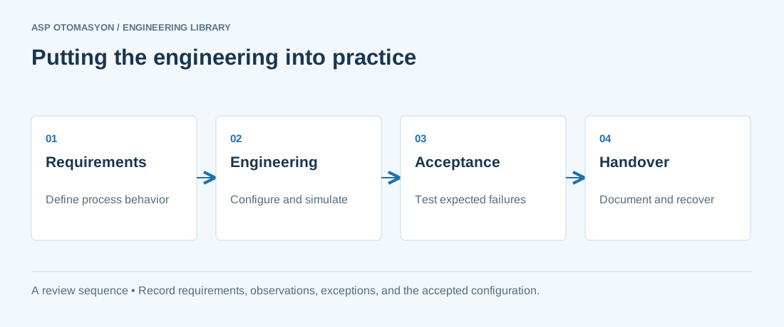
- Define the process states, timing requirements, and permitted behavior after a controller or communication failure.
- List controller, I/O, network, software, and license dependencies before choosing an architecture.
- Record acceptance results and prove that the delivered configuration can be restored from the handover package.
Follow an ASP project guide to connect the fundamentals with implementation and acceptance.
Primary references and further reading
Use the original specifications and product documentation for implementation details. The examples in this guide are illustrative engineering scenarios, not published project results.