
Redundant control systems keep a plant running when hardware fails. In continuous process industries — refining, petrochemicals, power, pipelines — a control system outage can mean a full process trip, product loss, and restart costs that dwarf the price of redundancy. This article explains the common redundancy architectures, how failover actually works, and the design decisions that determine whether redundancy delivers its promised availability.
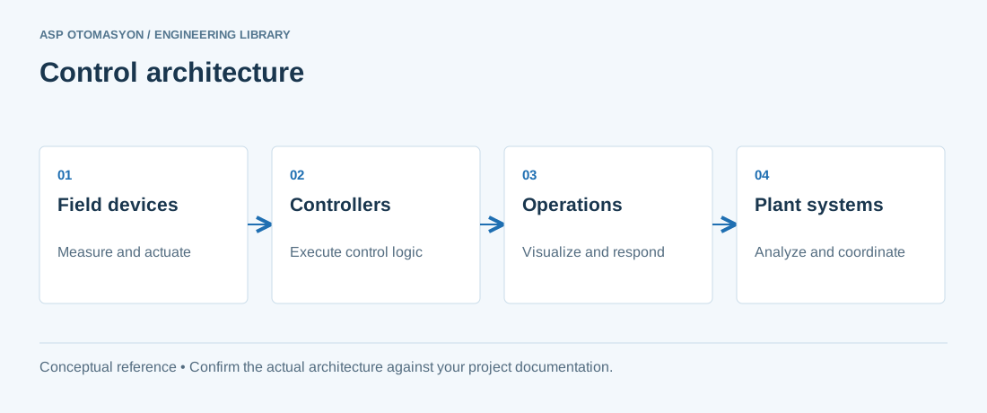
What Redundancy Is (and Is Not)
Redundancy means duplicating critical components so that a single failure does not interrupt control. It is a tool for increasing availability, not a substitute for reliability or for a sound safety design. A redundant system still needs:
- Redundant power supplies and UPS
- Redundant network paths (dual LAN, ring topologies)
- Redundant field wiring where justified (dual transmitters, dual valves)
- Recovery procedures for the cases redundancy cannot cover (common-cause failures, software defects)
Redundancy Architectures
| Architecture | How it works | Failure tolerance | Typical use |
|---|---|---|---|
| Hot standby (1oo2) | Two controllers run in parallel; the standby tracks the active unit; on failure the standby takes over automatically | 1 failure | DCS/PLC control of critical loops |
| Dual (2oo2) | Both units must agree; output is enabled only when both agree | Fail-safe on disagreement (trip) | Safety systems, burner management |
| Triple modular redundancy (2oo3) | Three units vote; the majority decides | 1 failure without losing function | High-integrity safety and critical control |
| N+1 / N+2 (power, networks) | Extra parallel units share the load | 1–2 failures depending on N | Power supplies, fans, network switches |
In the widely used notation, 1oo2 means "1 out of 2 needed to operate" — the hot-standby control architecture — while 2oo2 means "2 out of 2 needed to operate", a fail-safe arrangement used in safety applications where a disagreement must trip the process.
How Hot-Standby Failover Works
A typical hot-standby PLC/DCS pair performs these functions continuously:
- Synchronization: the standby unit receives a copy of the active unit's process image, program state, and timer/counter values over a dedicated sync link.
- Health monitoring: each unit monitors the other's heartbeat and its own self-test results.
- Bumpless transfer: on failover, the standby assumes control with outputs matching the last known active state, so the process does not see a bump.
- Return to service: after repair, the failed unit re-synchronizes and returns to standby — the system must support online resynchronization without a process disturbance.
The sync link is the most critical part of a redundant pair. It must be fast, reliable, and ideally duplicated. Many vendors require the sync link to be the first thing installed and the most carefully maintained connection in the cabinet.
Design Decisions That Decide Real Availability
- I/O strategy: redundant controllers with single I/O are only half-redundant. Decide whether I/O racks, fieldbus segments, and field devices are also duplicated, and understand what the controller can and cannot survive.
- Failover triggers: what events cause a transfer? Processor fault, watchdog trip, power loss, communication loss? A too-sensitive failover can cause nuisance transfers that disturb the process more than the original fault.
- Common-cause failures: two identical units in the same cabinet share power, temperature, and firmware — a single design flaw or a firmware bug can take down both. Redundancy does not protect against common-cause events.
- Software changes: the most common cause of dual failure is a faulty download or a program change applied inconsistently. Use the vendor's supported online-change procedure and verify both units are running identical firmware and logic.
- Testing: a standby that has never failed over is unproven. Schedule regular, controlled failover tests (during planned shutdowns where possible) and document the behavior.
Redundancy for Communications and Power
Controllers are not the only single point of failure. A complete redundant architecture typically includes:
- Redundant power: dual power supplies with diode OR-ing, fed from separate mains and/or UPS sources.
- Redundant networks: dual Ethernet adapters, ring topologies with rapid spanning tree (RSTP/MRP), or parallel redundancy protocol (PRP/HSR) for zero-recovery-time networking.
- Redundant gateways/servers: for OPC and SCADA interfaces, active/passive gateway pairs with automatic failover.
Summary
Redundancy is a disciplined engineering decision, not a checkbox. Choose the architecture (hot standby, dual, or TMR) based on the process risk and the failure mode you must survive; design the power, network, and I/O layers to match; test failover behavior; and maintain the sync link as the crown jewel of the system. A well-designed redundant system is invisible in normal operation and earns its cost exactly once — the day a component fails and the plant keeps running.
Apply this to your project
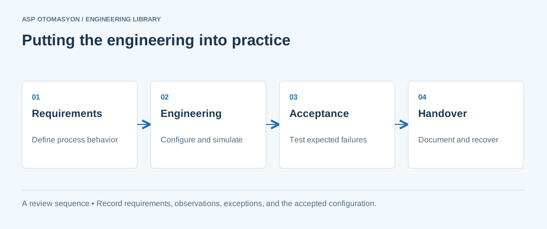
- Define the process states, timing requirements, and permitted behavior after a controller or communication failure.
- List controller, I/O, network, software, and license dependencies before choosing an architecture.
- Record acceptance results and prove that the delivered configuration can be restored from the handover package.
Follow an ASP project guide to connect the fundamentals with implementation and acceptance.
Primary references and further reading
Use the original specifications and product documentation for implementation details. The examples in this guide are illustrative engineering scenarios, not published project results.