
Connecting PLCs to SCADA is the integration task at the heart of most industrial monitoring projects. The SCADA system needs reliable, timely, and correctly typed data from every controller on the site, and the connection must survive field realities: noisy networks, device restarts, firmware quirks, and occasional bad engineering. This article covers the communication architecture, the protocols in common use, the configuration decisions that matter, and the validation steps that turn a "connection" into dependable data.
The Communication Stack
A typical PLC-to-SCADA path has four layers:
PLC (controller) ── driver/protocol ── network ── SCADA server (driver, tags, HMI)
                                    │
                                    └── gateway/middleware (OPC UA) ── optional
- The driver — SCADA software speaks to each PLC family through a vendor-specific driver (e.g., Siemens S7, Allen-Bradley CIP/EtherNet-IP, Modbus TCP, PROFINET). The driver handles the protocol details.
- The network — almost always Ethernet today (EtherNet/IP, Modbus TCP, S7 over TCP/IP), sometimes serial (Modbus RTU, RS-485) for legacy devices.
- Optional middleware — an OPC server (KEPServerEX, and similar) normalizes PLC data into OPC DA/UA, so SCADA and other consumers share one integration point.
- The SCADA tag layer — driver addresses are mapped to named tags that the HMI and historians reference.
Choosing the Integration Approach
| Approach | Advantages | Considerations |
|---|---|---|
| Direct driver (SCADA ↔ PLC) | Lowest latency, simple, no extra license | One driver per PLC type; less flexible for many consumers |
| OPC UA middleware | One interface for all consumers, richer data model, security built in | Extra software layer, licensing, must be maintained |
| Gateway/edge device | Isolates networks, buffers data, protocol conversion | Another device to manage; adds latency |
Small single-vendor sites often use direct drivers; multi-vendor plants and plants with many data consumers almost always benefit from an OPC UA middleware layer.
Configuration Essentials
Tag mapping and data types
Each PLC address must map to a SCADA tag with the correct type:
- Discrete: bit/Boolean — verify the byte and bit order when mapping words.
- Analog: integer (INT/DINT) or real (REAL) — know the PLC's data format (e.g., Siemens S7 REAL vs. IEEE-754, Modbus register pairing for 32-bit values).
- Scaling: many drivers deliver raw values; apply scaling (raw-to-engineering units) consistently, ideally in one place (SCADA tag) so everyone agrees on the units.
Polling and update rates
Drivers poll registers on a schedule. Set realistic polling rates:
- Fast process values: 100 ms–1 s
- Status and slow analogs: 1–10 s
- Event-driven data (where supported): on change, to reduce network load
Aggressive polling of thousands of tags on a shared network causes jitter and missed deadlines. Prefer drivers that support on-change reporting and deadbands.
Quality and status handling
Treat data quality explicitly: drivers report "bad quality" when a PLC is offline or a read fails. Design the HMI to display quality (e.g., stale/greyed values) rather than showing old data as if it were live. Define what happens to history during outages (buffering at the driver vs. gaps).
Reliability Design
- Redundant paths: dual Ethernet adapters or redundant ring networks for critical controllers; SCADA servers with failover.
- Reconnection behavior: the driver must reconnect automatically after a PLC restart, and the SCADA should recover tags without a full restart.
- Watchdogs/heartbeats: use a periodic "PLC alive" signal (a toggling tag or a health status) so the operator knows the link is healthy, not just silent.
- Network hygiene: keep SCADA traffic on the OT network, use managed switches, and follow segmentation (see the Purdue Model article) so SCADA polling does not collide with control traffic.
Validation Before Commissioning
- Address verification: for a sample of tags, force known values in the PLC and confirm the SCADA displays them correctly (including negative values, zero, and extremes).
- Type check: confirm 32-bit and floating-point values are interpreted correctly end-to-end.
- Latency measurement: measure update latency for the fastest tags; it should match the polling configuration.
- Outage test: pull the network cable from a PLC; verify the SCADA flags bad quality, and recovers cleanly when reconnected.
- Restart test: reboot the PLC and the SCADA server; verify tags repopulate without manual intervention.
Common Pitfalls
- Byte-order and word-order mismatches — the classic Modbus/S7 32-bit headache; validate with a known value before wiring hundreds of tags.
- Register overlap — reading the same data via different blocks can cause inconsistent snapshots; keep one canonical mapping.
- Polling storms — too many tags at too fast a rate degrade the network; use on-change and deadbands.
- No quality handling — stale data presented as live is a safety and decision-making hazard.
- Unmaintained address map — when PLC code changes, the SCADA mapping must be updated in the same change window; document and version the mapping.
Summary
PLC-to-SCADA integration is straightforward when the foundations are right: choose the integration approach that matches the plant's scale, map tags with correct types and scaling, configure realistic polling, design for quality and reconnection, and validate with outage and restart tests. The result is monitoring data that operators can trust — which is the entire point of the SCADA layer.
Apply this to your project
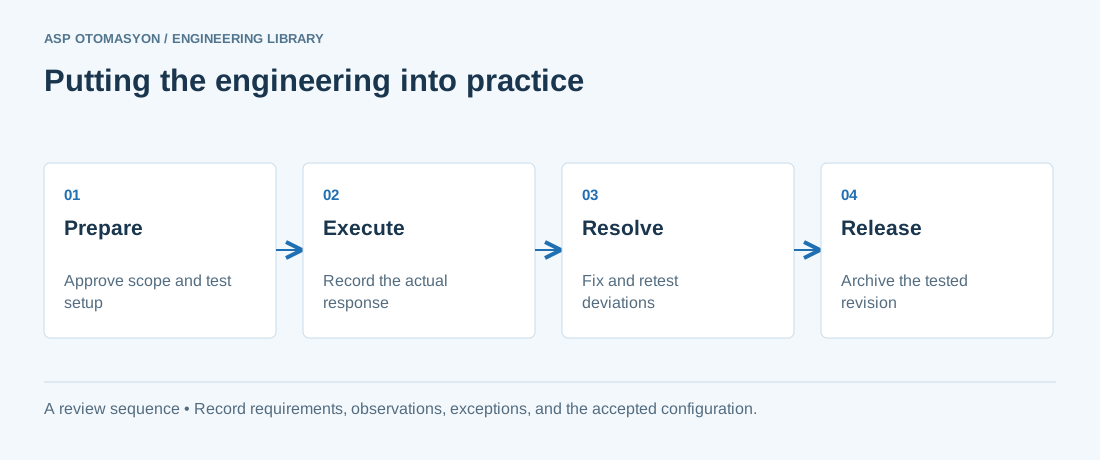
- Agree the test boundary and site authorization, especially where outputs or communications can affect operating equipment.
- Record expected and actual values, equipment identifiers, software revision, test conditions, and exceptions.
- Retest changed behavior and archive the final configuration with the test record and recovery instructions.
Follow an ASP project guide to connect the fundamentals with implementation and acceptance.
Primary references and further reading
Use the original specifications and product documentation for implementation details. The examples in this guide are illustrative engineering scenarios, not published project results.