
Half of all "mystery" automation faults — random PLC inputs, drifting analog readings, resets at odd times — are electromagnetic interference (EMI) problems in disguise. The cure is almost never more shielding or better PLCs; it is correct grounding and bonding. Grounding provides a safe fault-current path; bonding equalizes potential between metal parts; and the combination, executed with discipline, keeps noise currents out of the signal paths. This article explains the principles that make installations immune.
Grounding vs Bonding
- Grounding — connecting electrical systems and equipment to the earth electrode system: it establishes a reference potential and provides the fault-current path that lets protective devices operate.
- Bonding — connecting all exposed metal parts (enclosures, conduits, cable trays, machine frames) together so they sit at the same potential. Bonding prevents touch voltages and eliminates the current paths between equipment that cause noise.
The rule of thumb: everything metallic in the industrial environment is bonded; one grounding system serves the whole facility — separate "clean" grounds for instruments are a myth that creates exactly the potential differences they claim to avoid. Signal reference, safety ground, and structural steel should all tie into the same single-point ground network.
Why Noise Happens
Interference reaches signals by four mechanisms:
- Conduction — noise rides in on the supply or shared return wires; e.g., a PLC sharing a 24 V rail with contactors.
- Capacitive coupling — fast-changing voltage (VFD output, relay coil switching) couples into nearby signal wires through the parasitic capacitance between them.
- Inductive coupling — changing current (motor leads, welding) induces voltages into loops formed by signal wiring.
- Ground loops — signal wires grounded at both ends create a loop; any current in the ground path (from other equipment) flows through the signal return and injects an offset that varies with load — the classic cause of analog drift.
Note the asymmetry: motors and VFDs create noise; sensors and controllers receive it. The fix targets the coupling path and the receiver, not the source.
Grounding Practice That Works
- Single-point (star) grounding for control systems — signal commons, shields, and control grounds meet at one panel reference point, connected to the facility ground by a dedicated conductor. Multiple reference points create loops.
- Shield termination — shields are grounded at one end only for analog signals (typically at the panel), or both ends with a parallel drain for data cables where the standard requires it. Unconnected shield tails are antennas; connected-both-ends shields are ground-loop creators.
- PE conductor discipline — a dedicated protective earth conductor from the panel's PE bus to the facility ground, sized per the fault current, never shared with signal returns, never carrying control current.
- Bonding mesh — enclosures, trays, and conduits bonded to the ground grid with short, low-impedance connections; a floating panel door or tray section becomes an antenna.
- Equipotential between panels — panels in a line must sit at the same potential; the ground grid (and where required, a dedicated equipotential bar) provides it.
VFDs and Noise
Variable frequency drives are the loudest noise sources in most plants. Practical containment:
- Ground the motor and the drive with short, direct, dedicated conductors; the motor cable is a noise source along its whole length.
- Use shielded VFD output cable (or an unshielded cable in steel conduit), shield grounded at both ends for the high-frequency currents, and keep the cable completely separate from signal wiring.
- Install the drive's EMC filter (or motor choke) as designed; removing it to save a bracket is how noise problems are installed.
- Common-mode chokes and proper cable glands (360° shield contact) eliminate the residual high-frequency currents on long runs.
Diagnosing Noise Faults
When interference is suspected, measure before touching:
- Log the fault pattern: does the analog drift track with a motor starting? Is the false input at a fixed time of day (another process running)?
- Measure the signal at the PLC terminal with a scope or logging meter during the fault — is the noise on the signal, the common, or the supply?
- Check potential differences between panel, machine frame, and ground bus with a voltmeter — millivolts are fine; volts are the diagnosis.
- Test the hypothesis: unplug the field cable (does the fault disappear?), move the cable (coupling distance), add a capacitor/ferrite as a temporary probe — then implement the permanent fix: proper shield termination, routing separation, or supply filtering.
The discipline is to change one variable at a time and verify; plants that "fix" noise by swapping PLCs or adding filters everywhere never find the cause.
Summary
Noise immunity comes from grounding architecture, not lucky shielding: one facility ground, bonded metal everywhere, single-point signal reference, shields terminated with intent, VFDs contained at the source, and signal wiring routed away from power. When faults appear, measure the coupling path and fix the cause. Grounding done right is invisible; grounding done wrong shows up at 3 a.m. — and always will.
Apply this to your project
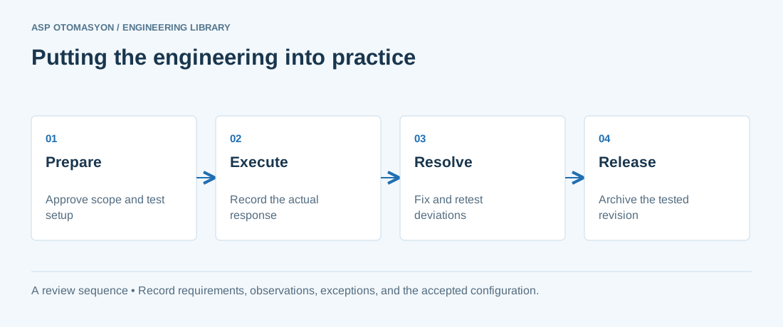
- Agree the test boundary and site authorization, especially where outputs or communications can affect operating equipment.
- Record expected and actual values, equipment identifiers, software revision, test conditions, and exceptions.
- Retest changed behavior and archive the final configuration with the test record and recovery instructions.
Follow an ASP project guide to connect the fundamentals with implementation and acceptance.
Primary references and further reading
Use the original specifications and product documentation for implementation details. The examples in this guide are illustrative engineering scenarios, not published project results.