
Industrial Ethernet's reliability is decided in the cable plant long before any packet is sent. Office-grade components installed in a machine environment produce intermittent faults that are nearly impossible to trace; properly selected and installed industrial cabling — connectors, cables, and pathways — runs for decades without attention. This article covers the physical layer decisions that determine network availability: cable categories, connector types, installation practice, and documentation.
Cable and Connector Selection
Industrial environments demand components rated for the real conditions: temperature, oil, flexing, vibration, and washdown:
- Channel category — Cat 5e (100 MHz) supports 100BASE-TX and is adequate for most field networks; Cat 6a/6 (500/250 MHz) for 10GBASE-T backbones and future-proof trunks. What matters is the installed channel certification, not the box label.
- Cable type — for machine areas: flexible, oil-resistant (PUR/TPE jacket) cables; for fixed tray runs: flame-retardant, UV-resistant jackets. Standard office patch cables are the wrong tool in both.
- Connector type — RJ45 (IP20) in cabinets, M12 D-coded or X-coded (IP65/67) at machine and field devices, M8 for small sensors, and fiber (LC) for long runs and noisy zones. Field-mounting RJ45 in an IP65 box is a downgrade; choose the connector to the environment, not the habit.
- Pre-made vs field-terminated — factory-terminated, tested patch cords for device connections; field termination only where lengths force it, with the right tooling and a tester after every termination.
Installation Rules
- Separation from power — signal cables at least 20 cm from 230/400 V cables, more (30–50 cm) from VFD motor cables; cross at 90° where unavoidable. Cables in the same tray as motor leads are a design error.
- Bend radius and strain — respect the cable's minimum bend radius (typically 8–10× outer diameter for flexible cables), avoid sharp edges, and relieve strain at every termination and hatch; flexible cables on moving parts need drag-chain ratings.
- Pathways — dedicated trays or conduits with separation from power; open tray for heat, conduit where mechanical protection matters; avoid running cables near heat sources and in condensate paths.
- Bonding of pathways — metallic trays and conduits bonded to the ground grid (see grounding practice) so a fault current on a tray does not become a noise source or a fire risk.
- Length discipline — permanent-link runs limited per the channel standard (100 m copper), fiber for longer; document actual lengths — the network design depends on them.
- Labeling — every cable labeled at both ends with the network design's identifier; patching is impossible to verify without labels.
Structured Cabling Topology
Industrial installations benefit from the same structure as office networks: permanent links (field to cabinet/panel) terminated on patch panels, patch cords inside the cabinet to switches, and trunk cables between cabinets. The structure means a device can be moved, a switch replaced, or a port re-assigned without touching the permanent link — and every change is recorded in the patching documentation. For machines, the same principle scales down: a small patch panel or pluggable connectors per section keeps the machine serviceable.
Fiber Where It Counts
Fiber optic cabling earns its place in three situations: runs over 100 m (plant backbone), electrically noisy environments (VFD rooms, welding cells), and inter-building links (including lightning risk areas). Multi-mode OM3/OM4 for intra-plant distances; single-mode OS2 for long or future-proof routes. Fiber also breaks ground loops and galvanic isolation problems — a legitimate reason to use it even for short hops in power environments. Terminate with factory connectors or a proven splice; a field splice kit without training is a future attenuation mystery.
Testing and Documentation
Every permanent link gets certified at installation: wire map, length, attenuation, and return loss against the category limit — with a tester, not a continuity lamp. The test results are the infrastructure's birth certificate; store them with the network documentation (the physical topology drawing, cable schedule, and label list). When a fault appears years later, the documentation separates "the link was always bad" from "something changed."
Summary
Industrial Ethernet cabling is an engineering decision: components rated for the environment, connectors matched to the exposure, separation from power, structured topology with labeled permanent links, fiber where distance or noise demands, and every link certified and documented. The network's availability is decided here — a properly installed cable plant makes the upper layers boring, and boring is the goal.
Apply this to your project
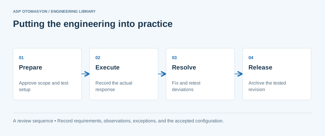
- Agree the test boundary and site authorization, especially where outputs or communications can affect operating equipment.
- Record expected and actual values, equipment identifiers, software revision, test conditions, and exceptions.
- Retest changed behavior and archive the final configuration with the test record and recovery instructions.
Follow an ASP project guide to connect the fundamentals with implementation and acceptance.
Primary references and further reading
Use the original specifications and product documentation for implementation details. The examples in this guide are illustrative engineering scenarios, not published project results.