
A redundant industrial network needs a protocol matched to its topology and device support, plus a failover test that records what the control system actually sees.
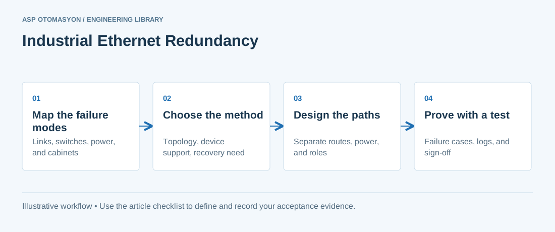
Industrial networks are often built with a second path so that one failure does not stop control. The second path is not redundancy by itself. A cable that closes a loop creates a loop, and an unmanaged loop can flood a network with frames. Redundancy exists only when a protocol decides which path carries traffic, detects a failure, and restores service, and when the two paths do not share the same weak point.
This article compares the main approaches used on Ethernet plant networks: RSTP, MRP, PRP, and HSR, with ODVA's Device Level Ring (DLR) as the ring method used with EtherNet/IP. It covers the design choice, a selection table, checks for single points of failure, and a failover test plan. Recovery behavior is set by each product's documentation and must be measured on site. This article does not quote recovery times.
Why a second cable is not enough
Ethernet frames carry no hop limit that stops a loop from circulating. A cable that connects two switches already joined by another path creates a loop that broadcast and multicast frames can travel around indefinitely. The protocols in this article prevent that loop in different ways. Each one also changes the active path when a link or switch fails, and that change is where designs succeed or fail.
Redundancy must also be assessed on the physical side. Two paths that run in the same cable tray, share one power supply, or pass through one switch cabinet form a single point of failure with two cables. No protocol can fix that, so the design review must examine the physical layout as well as the topology diagram. The cabling choices behind this are covered in industrial Ethernet cabling and infrastructure design.
RSTP: reconverging a spanning tree
The Rapid Spanning Tree Protocol (RSTP) belongs to the IEEE 802.1 bridging family. It is specified in IEEE 802.1D and carried into the IEEE 802.1Q bridge standard in later editions. RSTP builds a loop-free tree by blocking some ports. When a link or switch fails, the switches recompute the tree and move ports to forwarding. The recovery time depends on the topology, on settings such as edge-port and link-type configuration, and on how each switch implements the protocol.
RSTP is a general-purpose mechanism. It is not built around the timing of one device family, so a control engineer should confirm how the controllers and I/O react during reconvergence rather than assume that a fast protocol name guarantees a fast control result. For switch fundamentals, see industrial Ethernet switching fundamentals.
Ring protocols: MRP and DLR
A ring connects each device to two neighbors, with one link blocked in normal operation. MRP (Media Redundancy Protocol), specified in IEC 62439-2, uses a ring manager to block one port and to react when the ring breaks. Its roles and recovery behavior come from the standard and the vendor documentation, so check each device's support list.
ODVA's Device Level Ring (DLR) is the ring protocol used with EtherNet/IP. The ODVA guidelines describe a ring supervisor that blocks traffic on one of its ports to avoid a loop, verifies the integrity of the ring, and reconfigures the ring after a fault. The guidelines strongly recommend at least one backup supervisor. Each supervisor has a precedence value. The highest precedence becomes active, and if two supervisors share a precedence, the higher MAC address wins.
Parallel protocols: PRP and HSR
The Parallel Redundancy Protocol (PRP) and the HSR ring variant are specified in IEC 62439-3. Both send duplicate frames over two independent paths. PRP uses two separate networks, and each device connects to both. HSR uses a ring in which frames are duplicated and travel in both directions. The receiving device accepts the first copy it gets and discards the other, so a single failure on one path leaves the other copy in place. The IEC webstore describes both protocols as designed to recover from a single failure of a link or bridge by sending the information in parallel; the real effect on a process must still be measured.
These methods need device support. A PRP device needs two network interfaces, one on each network. An HSR device needs ports that can join the ring. A device with a single interface needs a bridging element to attach to the redundant network.
Selection table by topology, recovery, and device support
The table compares the five methods for a first decision. Recovery behavior is described in qualitative terms only. Take any timing from the device documentation for the firmware in use, and measure it on site.
| Method | Specification owner | Topology | Recovery behavior (qualitative) | Device support check |
|---|---|---|---|---|
| RSTP | IEEE 802.1 bridging standards | Switched network with a loop-free tree | Recomputes the tree after a topology change; time depends on settings and implementation | Confirm RSTP and edge-port settings in each managed switch |
| MRP | IEC 62439-2 | Single ring | Ring manager reconfigures on a break; time from device documentation | Ring manager and ring client roles supported by each device |
| DLR | ODVA, with EtherNet/IP | Single ring | Ring supervisor reconfigures on a fault; time from device documentation | Ring supervisor, backup supervisor, and beacon or announce node support |
| PRP | IEC 62439-3 | Two separate networks, A and B | Duplicate frames on both networks; the receiver uses the first copy | Two network interfaces per device, one on each network |
| HSR | IEC 62439-3 | Ring with duplicated frames in both directions | Duplicate frames keep delivery on the surviving path | HSR-capable ports; single-interface devices need a bridging element |
Design checks for single points of failure
Check the drawing, then the cabinet and the route, because a single point of failure usually hides in the physical layout.
- Trace each path physically. Confirm that the two paths use separate cable routes, tray runs, and entry points into each cabinet.
- Check power for each switch. Confirm that each switch on each path has its own protected supply, and that the two supplies do not share one breaker or one upstream panel.
- Separate the networks for PRP. Confirm that network A and network B share no switch, no power supply, and no uplink.
- Document the protocol roles. For RSTP, MRP, and DLR, record the root bridge, ring manager, or ring supervisors, their backups, and their precedence settings.
A failover test plan with evidence
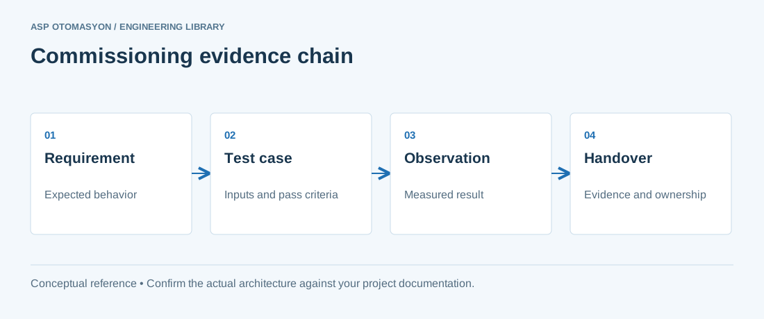
A redundancy design is not proven until a failure has been applied and the result recorded. Agree the acceptance rules with the process owner before the test, and link the test to the wider redundancy failover acceptance procedure for the control path.
- Define the failure cases. Include a single link cut, a switch power loss, a device power loss, and a ring supervisor or root failure where the design has one.
- Set the acceptance rule. Agree with the process owner what the control system must do during and after each case, and how much stale data is acceptable.
- Record at both ends. Capture timestamps at the controller, the operator station, and a monitoring port, so the observed interruption can be checked against device logs.
- Repeat under load. Run each case with realistic traffic, and repeat it enough times to see variation rather than a single result.
- Retest after changes. Repeat the full set after any firmware, switch configuration, or topology change.
Apply this to your project
- Each redundancy method in the design is recorded with its specification owner, topology, and device support list.
- Recovery behavior values come from the device documentation for the firmware in use, and are labelled as such.
- The two paths share no cable route, switch, power supply, or cabinet at any point.
- Root bridge, ring manager, or ring supervisor roles and their backups are documented with precedence settings.
- Failover tests cover link, switch, and device failures, and are recorded at both the controller and the operator station.
- Test results are kept with the firmware and configuration versions that were tested.
Follow an ASP project guide to connect the fundamentals with implementation and acceptance.
Frequently asked questions
Why does a ring need a protocol at all?
A ring has a physical loop, and Ethernet switches forward broadcast frames, so an unmanaged loop can circulate traffic indefinitely. A ring protocol designates which port blocks traffic in normal operation, detects a break, and opens the blocked path. Without that role, the ring is a fault waiting to happen rather than a redundant design.
Is RSTP fast enough for control?
The answer depends on the topology, the settings, and the devices, so it cannot be decided from the protocol name. Use the switch documentation for the recovery behavior of the configuration in use, then measure the interruption seen by the controller under the failure cases the process needs. Do not accept a figure from a brochure without that measurement.
What is the difference between MRP and DLR?
Both are ring protocols with one blocked point in normal operation. MRP is specified in IEC 62439-2 and uses ring manager and ring client roles. DLR is the ODVA ring protocol used with EtherNet/IP and uses a ring supervisor with a precedence setting, plus beacon-based or announce-based ring nodes. Check which protocol each device supports before choosing, because one ring cannot simply mix both.
Do PRP and HSR need special devices?
Yes. Devices must support the protocol on their interfaces. A PRP device needs two network interfaces, one on each network, and an HSR device needs ports that can join the ring. A device with a single interface needs a bridging element to attach to the redundant network. Confirm the device support list and the cost of that element before selecting the method.
Can I rely on a vendor's recovery time in the design?
Use it only as a starting point. Recovery depends on the configuration, the number of hops, the traffic load, and the device implementation. Ask the vendor for the test conditions, then measure the interruption in your own topology with the same firmware and settings. Record the measurement as acceptance evidence.
Continue the engineering work
- Industrial Ethernet Switching Fundamentals
- Redundant Control System Architectures
- Industrial Network Troubleshooting Methodology
- Redundancy Failover Acceptance: Testing the Complete Control Path
- Industrial Ethernet Cabling and Infrastructure Design
Browse the related technical library or follow an ASP project guide to plan the implementation sequence.
Primary references and further reading
Use the original specifications and product documentation for implementation details. Examples in this guide are illustrative engineering scenarios, not published project results.