
Redundancy is useful only when the required function survives the failures the design intends to tolerate. A pair of servers does not prove controller, network, power, storage, client, or field-path resilience. Define the failure boundary and acceptance criteria for each function before testing.
Design the requirement before the configuration
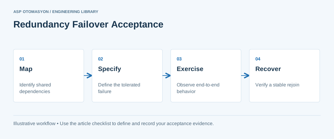
Map primary and standby components along the complete path and identify shared dependencies. Document detection time, switchover behavior, permitted interruption, retained state, and recovery to a stable configuration. Distinguish automatic failover from manual restoration and from recovery after multiple faults. Use an approved test plan with operational safeguards; do not disconnect plant equipment simply to see what happens.
Worked scenario
In an illustrative SCADA pair, the standby server becomes active but clients continue trying the failed address. Server-role switchover succeeded while operator access did not. A complete test observes the client session, displayed quality, alarms, writes where safely authorized, historian continuity, and the path back to normal operation.
What to verify
| Check | Evidence to record |
|---|---|
| Dependency | Power, network, storage, identity, time, and licenses |
| Failure | One specifically defined fault per approved test |
| Continuity | Client behavior, process state, data quality, and history |
| Recovery | Rejoin, resynchronization, and prevention of conflicting active roles |
Acceptance and handover
Capture timed observations at both endpoints and preserve relevant logs. Repeat representative failures under expected peak load and document any excluded fault combinations. A successful test supports only its stated scenario; keep those boundaries visible in the handover record.
Continue the engineering work
Use the related technical library for deeper background, or follow an ASP project guide to plan the implementation sequence.
Primary references and further reading
Use the original specifications and product documentation for implementation details. The examples in this guide are illustrative engineering scenarios, not published project results.