
The PLC scan cycle is the fundamental execution model of every programmable logic controller. Unlike a general-purpose computer, which runs many programs concurrently under an operating system, a PLC executes a single control program in a continuous, repeating loop. Understanding this loop — what happens in each phase, how long it takes, and how to design logic around it — is essential for writing reliable control programs and for diagnosing timing-related faults on the plant floor.
The Four Phases of a Scan
A typical PLC scan consists of four phases executed in strict order:
- Read inputs — the CPU copies the physical state of all input modules into an internal input image table in memory.
- Execute program — the CPU runs the user program sequentially, reading and writing only to the image tables, never directly to the physical modules.
- Write outputs — the output image table is copied to the physical output modules.
- Housekeeping — communication with HMI/SCADA, programming tools, and other CPUs; diagnostics; self-test.
Using image tables means that a program reads a consistent snapshot of the inputs for the whole scan. If an input changes mid-scan, the change is not seen until the next scan. This consistency is intentional: it makes program behavior deterministic and much easier to reason about.
Scan Time and Its Limits
Scan time is the total time for one complete cycle and is typically measured in milliseconds. A small program on a modern PLC may scan in under 1 ms; a large program with extensive analog processing may take 10–50 ms. Key factors that increase scan time:
- Program size and instruction mix (floating-point math and string operations are slower than bit logic)
- Number of I/O points, especially analog and high-speed modules
- Communication tasks: HMI polling, SCADA traffic, peer-to-peer messaging, web servers
- Diagnostics and trend buffers enabled on large tag sets
Every PLC has a configurable watchdog timer. If a scan exceeds the watchdog value, the CPU typically stops program execution, sets the outputs to a safe state, and reports a fault. The watchdog is a safety mechanism, not a tuning tool: it should be set generously above the observed maximum scan time so that occasional communication spikes do not trip it.
Task Models: Cyclic, Periodic, and Event-Driven
Modern controllers (IEC 61131-3 based, plus vendor platforms such as Siemens, Rockwell, and ABB) often support several task types instead of a single scan:
| Task type | Execution trigger | Typical use |
|---|---|---|
| Cyclic (free-running) | Continuously, as fast as possible | Main machine logic |
| Periodic (fixed interval) | Every configured time, e.g. 10 ms, 100 ms | Analog control loops, sequence steps |
| Event-driven | On a hardware or software event | Fast counting, interrupts, motion sync |
Periodic tasks are important for control loops because the sample time becomes deterministic: a PID loop executed in a 100 ms periodic task always samples every 100 ms regardless of what the cyclic task is doing. Mixing tasks requires care with shared data — use handshakes, semaphores, or synchronized copies when a fast task and a slow task access the same tag.
Determinism and I/O Response Time
The worst-case response time from a physical input change to a physical output change is roughly two scan cycles: the input is captured at the start of scan N, the program reacts, and the output is written at the end of scan N (or the input arrives just after the input read, pushing the response to scan N+1). This figure matters for safety and for fast processes. When a response must be faster than the scan allows, use:
- Hardware interrupt inputs or high-speed counters that bypass the scan
- Dedicated fast tasks (periodic or event-driven)
- Outputs with hardware interlocking (e.g., a hardwired e-stop chain)
For safety-related functions, always use certified safety controllers and hardwired safety circuits — do not rely on scan timing for personnel protection.
Design Practices Around the Scan
- Keep the critical path short. Move slow operations (string formatting, large data moves, file access) into slower tasks or background routines.
- Use edge detection consistently. A one-shot (rising-edge) instruction is evaluated once per scan; verify the scan rate matches your expectation of "once".
- Monitor scan time in the HMI. Trending scan time over weeks reveals creeping load from added logic or tags.
- Watch communication-induced jitter. Heavy HMI traffic can stretch scans; use scheduled/cyclic communication where the platform supports it.
- Document the task model. The maintenance engineer who inherits the machine needs to know which task runs what.
Summary
The scan cycle is the heartbeat of PLC operation. Designing programs that respect the read–execute–write model, choosing the right task type for each function, and monitoring scan time are basic but high-value habits. They prevent the classic field problems of intermittent timing faults, missed events, and control loops that behave differently in simulation than on the machine.
Apply this to your project
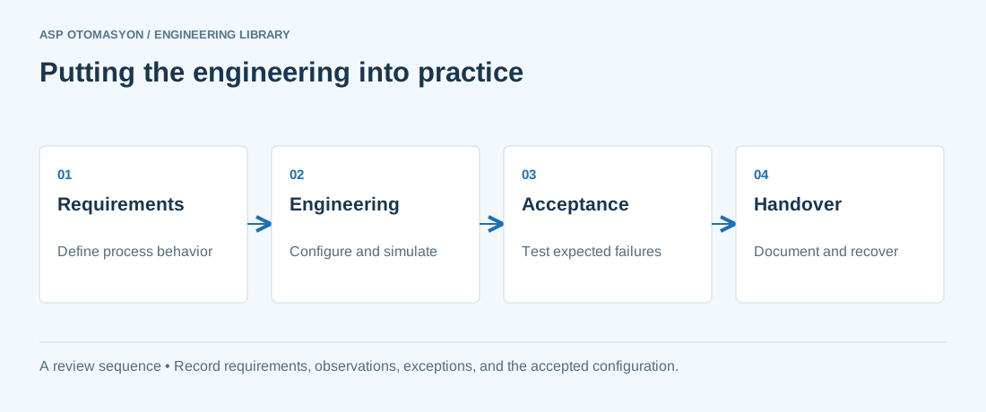
- Define the process states, timing requirements, and permitted behavior after a controller or communication failure.
- List controller, I/O, network, software, and license dependencies before choosing an architecture.
- Record acceptance results and prove that the delivered configuration can be restored from the handover package.
Follow an ASP project guide to connect the fundamentals with implementation and acceptance.
Primary references and further reading
Use the original specifications and product documentation for implementation details. The examples in this guide are illustrative engineering scenarios, not published project results.