
Power quality issues — voltage sags, harmonics, transients, and frequency variations — can cause equipment malfunctions, production downtime, and premature asset failure. Continuous power quality monitoring enables facilities to detect, diagnose, and mitigate these issues before they affect production.
IEC 61000 Standards Series — Application to Industrial Power Quality
The IEC 61000 series of standards, published by the International Electrotechnical Commission, addresses electromagnetic compatibility (EMC) and power quality. For industrial facilities, the most relevant parts include:
- IEC 61000-2-4 — Compatibility levels for low-frequency conducted disturbances in industrial plants. Defines voltage amplitude, harmonics, interharmonics, and unbalance limits at the point of coupling.
- IEC 61000-4-7 — General guide on harmonics and interharmonics measurement and instrumentation. Specifies the Fourier transform window width (200 ms for 50 Hz systems, 12-cycle) and aggregation intervals.
- IEC 61000-4-15 — Flickermeter functional and design specifications. Defines how voltage flicker (Pst and Plt) is measured.
- IEC 61000-4-30 — Power quality measurement methods. The most critical standard: it defines Class A (precision) and Class S (survey) measurement techniques for voltage, frequency, dips, swells, interruptions, harmonics, and flicker.
- IEC 61000-4-34 — Voltage dips, short interruptions, and voltage variations for equipment with rated current greater than 16 A.
Industrial facilities typically target compliance with the limits defined in IEEE 519-2022 for harmonic distortion at the point of common coupling (PCC) with the utility, while using IEC 61000-4-30 Class A instruments for verification measurements.
Power Quality Parameters — Detailed Explanation
Total Harmonic Distortion (THD)
THD quantifies the distortion of a voltage or current waveform relative to the fundamental frequency component. It is expressed as a percentage and calculated as:
THDV = (√(Σ Vh²) / V1) × 100%
where Vh is the RMS voltage of harmonic order h (typically h = 2 to 50) and V1 is the fundamental RMS voltage. Current THD (THDI) is calculated analogously. Typical IEEE 519 limits for general industrial systems: voltage THD ≤ 5%, current THD varies by the short-circuit ratio (Isc/IL). High THD causes transformer overheating, nuisance breaker tripping, motor torque pulsations, and capacitor bank failure.
Total Demand Distortion (TDD)
TDD is a variant of current harmonic distortion where the harmonic sum is referenced to the maximum demand load current (IL) rather than the fundamental current at the time of measurement. This avoids artificially high distortion readings during periods of light load. TDD is calculated as:
TDD = (√(Σ Ih²) / IL) × 100%
IEEE 519-2022 specifies TDD limits based on the ratio of the short-circuit current (Isc) to the average maximum demand load current (IL). A higher Isc/IL ratio allows higher TDD because the system is stiffer and can tolerate more harmonic injection.
Crest Factor
The crest factor (CF) is the ratio of the peak value of a waveform to its RMS value:
CF = Vpeak / VRMS
For a pure sine wave, CF = √2 ≈ 1.414. Power supplies, variable frequency drives, and other nonlinear loads draw current with high crest factors (2.0 to 3.0), which can cause saturation in transformers and nuisance fuse blowing. Monitoring crest factor provides insight into the severity of current waveform distortion beyond what THD alone reveals.
Voltage Sags, Swells, Transients, and Flicker
- Voltage sags (dips) — A reduction in RMS voltage to 10–90% of nominal for 0.5 cycles to 1 minute. Caused by motor starting, transformer energisation, or utility faults. IEC 61000-4-30 Class A instruments record sag magnitude and duration.
- Voltage swells — An increase in RMS voltage above 110% of nominal for up to 1 minute. Often caused by large load shedding or single-line-to-ground faults on an ungrounded system.
- Transients — Short-duration (nanoseconds to milliseconds) voltage or current spikes. Lightning strikes, capacitor switching, and arc flash events produce transients that can damage sensitive electronics.
- Flicker — Rapid, repetitive voltage fluctuations perceived as light flicker. IEC 61000-4-15 defines the Pst (short-term, 10-minute) and Plt (long-term, 2-hour) flicker indices. Common sources include arc furnaces, welders, and large motor drives.
Power Quality Monitoring Equipment — Selection Criteria
Selecting the right PQ monitoring equipment depends on the measurement objective, installation type, and required accuracy:
- IEC 61000-4-30 Class A — Highest accuracy, required for compliance verification, contractual disputes, and certification. These instruments have tight tolerances on measurement uncertainty (e.g., ±0.1% for voltage, ±0.01 Hz for frequency) and synchronised measurement intervals. Examples include Fluke 1760, Dranetz HDPQ, and Elspec G4500.
- IEC 61000-4-30 Class S — Survey-grade accuracy (±0.5% voltage, ±0.03 Hz frequency). Suitable for general PQ assessment, energy management, and trend analysis. Most power quality analysers and revenue meters offer Class S measurement.
- Permanent vs. Portable — Permanent monitors are installed at critical buses (PCC, UPS outputs, sensitive process feeders) for continuous surveillance with alarm notification. Portable analysers are moved from point to point for troubleshooting, pre-qualification studies, and temporary surveys.
Data Interpretation and Trend Analysis
Raw PQ data is voluminous; interpretation requires statistical reduction and event classification. Modern PQ software platforms provide:
- Statistical summaries — CP95 (95th percentile) values for each parameter over user-defined intervals (daily, weekly, monthly). CP95 is widely used to characterise "typical" PQ performance.
- Event classification per EN 50160 / IEC 61000-2-4 — Voltage events (sags, swells, interruptions) are categorised by depth and duration into classes. This allows facility engineers to assess whether PQ events are likely to disrupt sensitive equipment.
- Trend analysis — Long-term trends in THD, voltage unbalance, and flicker can reveal gradual degradation: filter bank detuning, capacitor ageing, or increasing nonlinear load penetration. Early detection allows proactive maintenance before process disruption occurs.
Mitigation Strategies
Active Harmonic Filters (AHF)
Active harmonic filters inject current that is equal in magnitude but opposite in phase to the harmonic currents drawn by nonlinear loads, achieving cancellation. Modern AHFs use IGBT-based inverters and DSP controllers to compensate up to the 50th harmonic simultaneously. They can be applied at the PCC (whole-plant compensation) or at individual loads. Sizing is based on the total harmonic current (ITHD) to be cancelled, typically 50–300 A per module in parallel configurations. Advantages include dynamic response, no resonance risk, and the ability to provide reactive power compensation as a secondary function.
Uninterruptible Power Supplies (UPS)
UPS systems protect critical loads — PLCs, DCS, servers, safety systems — against voltage sags, interruptions, and frequency variations. A double-conversion (online) UPS continuously rectifies incoming AC to DC and then inverts DC back to clean AC, providing complete isolation from utility disturbances. For industrial environments, UPS systems must be rated for the inrush currents of motor-driven loads and should include a maintenance bypass for safe servicing. Battery runtime is typically 5–30 minutes, with generator backup for extended outages.
Line Reactors and Isolation Transformers
Line reactors (AC input chokes) are installed in series with VFDs and other power electronics to limit the rate of rise (di/dt) of current transients, reduce harmonic injection, and protect the drive from voltage spikes. Typical impedance is 3–5% of the drive's rated impedance. Isolation transformers with electrostatic shielding provide galvanic isolation and common-mode noise attenuation, preventing ground loops and protecting equipment from transient surges. They also enable voltage matching (e.g., 480 V to 400 V) for international equipment.
Power Factor Correction and Resonance Risks
Power factor correction (PFC) capacitor banks are widely used to reduce reactive power charges and improve voltage regulation. However, capacitors form a series LC circuit with the system inductance, and if the resonant frequency coincides with a harmonic frequency produced by VFDs or other nonlinear loads, severe harmonic amplification can occur. This can lead to capacitor fuse blowing, capacitor failure, or even system resonance that amplifies harmonic distortion 5× to 10×. Mitigation includes using detuned (7% or 14% impedance) reactor-capacitor combinations that shift the resonant frequency below the first significant harmonic (typically 189 Hz for 7% detuning on a 50 Hz system).
Establishing a Power Quality Monitoring Program
A structured PQ monitoring program follows these steps:
- Define objectives — Compliance verification, problem diagnosis, or preventive monitoring determine instrument class, measurement points, and duration.
- Select measurement points — PCC, main switchboards, UPS output, and critical process feeders. More points provide better granularity but increase data management burden.
- Set measurement intervals — IEC 61000-4-30 specifies 10/12-cycle (200 ms) aggregation with 10-minute and 2-hour reporting intervals. Continuous monitoring requires robust data storage and communication (Ethernet, cellular).
- Configure alarming — Set thresholds for each parameter (e.g., THD > 8%, sag < 85% of nominal) to trigger notification via email, SMS, or SCADA integration.
- Establish reporting cadence — Monthly statistical reports for management, weekly trend reviews for engineering, and real-time event notification for operations.
- Periodic review and program adjustment — Re-assess measurement points and thresholds as facility loads and processes change.
ASP OTOMASYON A.Ş. and its subsidiaries OPCTurkey and ASP Dijital provide end-to-end industrial engineering solutions for process automation, data operations and AI.
References & Further Reading
- IEC 61000 Series — Electromagnetic Compatibility (EMC) — International standard series covering electromagnetic compatibility, including immunity and emission limits for industrial equipment and power quality parameters.
- IEEE 519-2022 — Harmonic Control in Electric Power Systems — IEEE standard defining voltage and current harmonic limits at the point of common coupling, including THD and TDD measurement methodologies.
- IEC 61000-4-30 — Power Quality Measurement Methods — International standard specifying the methods for power quality parameter measurement including voltage sags, swells, harmonics, and flicker.
- IEC 61557-12 — Power Metering and Monitoring Devices (PMD) — International standard for performance monitoring devices used in power quality measurement and energy management applications.
- IEC 62053-22 — Electricity Metering Equipment (Class 0.2S, 0.5S) — International standard for static electricity meters with accuracy requirements for power quality and energy monitoring applications.
Apply this to your project
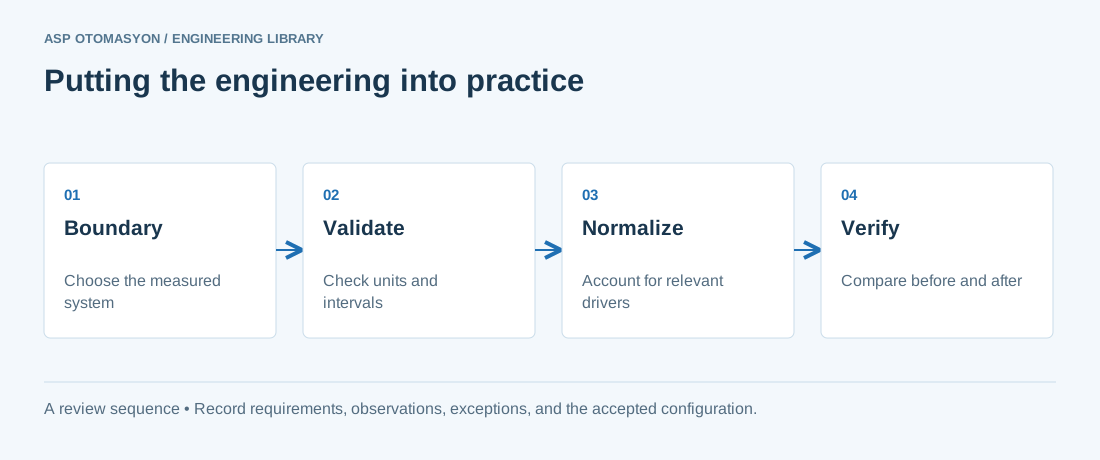
- Define the measurement boundary, meter ratios, units, time interval, and treatment of missing or reset readings.
- Capture production quantity, operating hours, and other relevant drivers alongside energy use.
- State the baseline and normalization assumptions when reporting a change; separate measured results from estimates.
Follow an ASP project guide to connect the fundamentals with implementation and acceptance.
Primary references and further reading
Use the original specifications and product documentation for implementation details. The examples in this guide are illustrative engineering scenarios, not published project results.