
Pressure measurement is the most widely used process measurement in industry after temperature. Pressure transmitters feed control loops, safety systems, and monitoring across every sector. Because the measurements feed decisions and interlocks, both the technology choice and the calibration practice matter: a pressure transmitter that drifts silently can cause quality problems, energy waste, or a trip of a safety system. This article covers pressure types, transmitter technologies, and a practical calibration program.
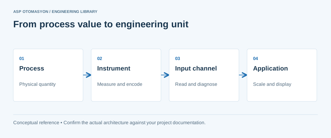
Pressure Definitions
| Type | Reference | Typical use |
|---|---|---|
| Gauge pressure | Atmospheric pressure | Most process measurements (e.g., vessel and line pressure) |
| Absolute pressure | Perfect vacuum | Vacuum systems, vapour pressure, altitude-sensitive processes |
| Differential pressure (DP) | Difference between two points | Flow (orifice), level (hydrostatic), filter monitoring, custody transfer |
| Vacuum | Below atmospheric | Evaporators, distillation, packaging |
Always state which reference applies — "10 bar" means different things as gauge vs. absolute, and the error can be fatal in vacuum or custody-transfer applications.
Transmitter Technologies
- Strain gauge (thin/thick film): the workhorse of process transmitters. A diaphragm deforms with pressure; bonded strain gauges measure the deformation. Robust, accurate (0.05–0.5% of span typical), and available in every range.
- Capacitive: a diaphragm moves between two capacitor plates; very stable and widely used in DP transmitters (e.g., classic capacitance-cell designs).
- Piezoelectric: generates a charge under pressure; used for dynamic pressure and high-frequency applications rather than steady process measurement.
- Resonant silicon: a silicon resonator's frequency changes with pressure; extremely stable and accurate, used in high-performance transmitters.
Modern smart transmitters add diagnostics: they detect diaphragm rupture, electronics faults, and (with additional sensors) line clogging and process anomalies — worth exploiting in the maintenance program.
Accuracy Terms
Read specifications precisely:
- Accuracy: usually expressed as % of span (e.g., ±0.075% of span) or % of reading for higher-end devices. Span is the calibrated range; the same transmitter can be recalibrated to a smaller span, but accuracy % of span then applies to the new span.
- Repeatability: how consistently the same input produces the same output.
- Drift: change in output over time at constant input — the reason calibration intervals exist.
- Temperature effect: error caused by ambient temperature change; important for outdoor and unheated installations.
Calibration Fundamentals
Calibration compares the transmitter's output against a known reference and adjusts it to meet specification. The essential equipment:
- Reference standard: a pressure source of known accuracy — deadweight tester (hydraulic or pneumatic) for high accuracy, or a calibrated pressure comparator/gauge for routine work. The reference must be calibrated itself and its accuracy must be better than the device under test (typically 3–4 times better).
- Readout: a current source/meter to read the 4–20 mA output, or a HART/Fieldbus communicator for digital calibration.
The calibration procedure (5-point method)
- Isolate the transmitter from the process and release trapped pressure; observe safety rules (process fluids, hot lines).
- Apply 0% input (LRV) and set the output to 4 mA.
- Apply 100% input (URV) and set the output to 20 mA.
- Check intermediate points (25/50/75%) and record the errors.
- Record the as-found and as-left values, the reference standard, date, and technician; store in the calibration management system.
Compare as-found against the allowed tolerance. If within tolerance, no adjustment is needed (some programs calibrate only on failure). If out of tolerance, adjust and retest.
Calibration Management
- Intervals: set initial intervals by vendor guidance and process criticality; extend or shorten based on as-found history. A transmitter that is consistently in tolerance can go longer; one that drifts needs shorter intervals or a different technology.
- Traceability: every calibration must trace back to national standards (through the reference's calibration certificate).
- Records: as-found/as-left data, tolerances, and history per instrument — this is both good engineering and a compliance requirement in regulated industries.
- Smart calibration: HART/Fieldbus transmitters can be calibrated digitally, with the digital value and the analog output verified separately (analog trim vs. sensor trim).
- Loop check: after calibration, verify the full loop (transmitter → I/O → SCADA/HMI) shows the correct engineering value — calibration alone does not prove the loop.
Common Pitfalls
- Reference accuracy too low: calibrating a 0.075% transmitter with a 1% gauge produces meaningless results.
- Confusing LRV/URV with physical range: a transmitter calibrated 0–10 bar measuring a 0–6 bar process still reads correctly, but resolution and accuracy suffer; set the span to the process.
- Zero shift after mounting: elevation/position changes affect some transmitters; zero after installation and after any physical disturbance.
- Impulse line problems: plugged, leaking, or gas-filled impulse lines produce readings that look like instrument drift but are actually process/wiring problems — check lines before recalibrating.
- Skipping the loop check: a perfectly calibrated transmitter connected to the wrong I/O channel still reports nonsense to the operator.
Summary
Pressure measurement is reliable when the technology matches the application and the calibration program is disciplined: proper reference standards, defined intervals driven by history, complete records, and loop verification after calibration. Choose the pressure type (gauge/absolute/DP) deliberately, read accuracy specs precisely, and treat impulse lines and the full loop as part of the measurement. The result is measurements that operators and control systems can trust for years.
Apply this to your project
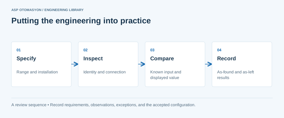
- Confirm the instrument tag, range, engineering unit, process connection, and environmental suitability against approved documents.
- Check the complete measurement chain, including sensor configuration, channel scaling, quality indication, and display units.
- Record reference equipment, uncertainty where relevant, test points, deviations, and the final configuration.
Follow an ASP project guide to connect the fundamentals with implementation and acceptance.
Primary references and further reading
Use the original specifications and product documentation for implementation details. The examples in this guide are illustrative engineering scenarios, not published project results.