
Level measurement is one of the most common — and most varied — measurement tasks in industrial automation. Tanks hold liquids, slurries, powders, and granules under pressures from vacuum to hundreds of bar and temperatures from cryogenic to molten. No single technology covers all applications, so selection is about matching the technology to the process: the medium, the vessel, the accuracy needed, and the maintenance environment. This article compares the main level technologies and gives a practical selection process.
Continuous Level Technologies
| Technology | Principle | Strengths | Limitations |
|---|---|---|---|
| Differential pressure | Pressure difference between two taps (or one tap + reference) proportional to hydrostatic head | Simple, proven, works in most liquids; no moving parts | Affected by density; needs correct tap placement; not ideal for solids |
| Radar (non-contact, FMCW) | Frequency-modulated microwave reflected from the surface | Accurate, no contact with medium, works on liquids and solids, unaffected by density/viscosity | Foam, vapour, and build-up can attenuate; dielectric constant matters; more expensive |
| Guided wave radar (GWR) | Pulse along a probe; reflection at the surface | Handles foam, vapours, low dielectric; good in small vessels and stilling wells | Probe contacts the medium (build-up, mechanical constraints); probe length limits range |
| Ultrasonic | Sound pulse reflected from the surface | Non-contact, cost-effective for simple liquids | Affected by temperature, vapour, foam, and turbulence |
| Capacitive / admittance | Capacitance between probe and vessel changes with level | Works on liquids, solids, interfaces; simple | Calibration-sensitive to product changes; coating effects |
| Hydrostatic (submersible / flush) | Pressure at a fixed point below the surface | Ideal for open tanks, sumps, wells | Density-dependent; requires submergence |
| Nuclear | Gamma radiation attenuation through the vessel | Non-contact, works through vessel walls, extreme conditions | Licensing, safety, and regulatory burden |
| Laser | Light reflection from the surface | Very narrow beam, good for small nozzles and solids | Affected by dust, steam, and surface colour |
Point Level Switches
For "is it empty / full / at this point" detection, switches are simpler and cheaper than continuous transmitters:
- Vibrating (tuning) fork — reliable for liquids and bulk solids; works in almost any medium; no calibration.
- Float / displacer — mechanical, proven, for liquids; moving parts need maintenance.
- Capacitive point switch — for solids and liquids; probe coating can cause false signals.
- Conductivity (resistive) — simple for conductive liquids; needs at least two electrodes.
- Optical — for liquids in clean small vessels (e.g., reservoirs); sensitive to contamination.
- Rotating paddle — common for bulk solids silos.
Many applications use a continuous transmitter for control plus one or two point switches as independent high/low alarms or interlocks.
Selection Process
- Define the medium: liquid, slurry, or solid? Dielectric constant (for radar), density (for DP), conductivity (for capacitive/conductivity), corrosiveness, and whether it coats, foams, or emits vapour.
- Define the process conditions: temperature, pressure, vacuum, agitation, boiling, and whether the surface is turbulent or foamy.
- Define the vessel: geometry (height, diameter), nozzle size and position, internal obstructions, stilling wells, and whether the vessel is open or closed (closed vessels need DP with two taps or a reference leg; radar handles them directly).
- Define the requirement: accuracy needed (control vs. inventory), range, response time, and whether interface level (two liquids) matters.
- Check the environment: hazardous area classification, vibration, ambient temperature, and installation access for maintenance.
- Shortlist and compare: for most liquid tanks, radar (non-contact) or DP are the defaults; for solids, radar or guided wave; for simple sumps, ultrasonic or hydrostatic; for extreme conditions, nuclear.
Installation and Calibration Notes
- Nozzle placement: radar beams need a clear path; avoid nozzles directly above fill inlets, and use stilling wells or bypass chambers where the surface is disturbed.
- Reference points: define the measurement range (from the empty reference to the full reference) and calibrate with the real medium where possible, not air.
- Density for DP: if the liquid density changes (temperature, product grade), DP level readings shift; either correct with density measurement or choose a technology that ignores density (radar).
- Verification: use a sight glass or tape measurement to verify the level at commissioning and periodically; smart transmitters store the verification results.
Common Pitfalls
- Foam: the technology that worked in the lab fails on a foaming process — check foam behaviour explicitly.
- Build-up and coating: probes that foul give drift and false readings; schedule cleaning or choose non-contact.
- Wrong tap placement: DP taps too close to inlets or outlets read turbulence, not level.
- Ignoring the interface: in a tank with two phases (water under oil), a single level transmitter reads the wrong interface; choose interface-capable measurement (GWR, capacitance, or DP with density correction).
- Over-specifying: a tuning-fork switch and a DP transmitter often beat a complex radar on a simple sump — match the tool to the job and the budget.
Summary
Level measurement selection is a matching exercise: medium, process conditions, vessel geometry, accuracy, and environment point to a shortlist of technologies, and the final choice balances performance against cost and maintenance. Radar and DP cover most liquid duties; guided wave handles difficult liquids; ultrasonic and hydrostatic suit simple tanks; and switches provide reliable alarm points. Verify the installation against a known reference and review the choice whenever the process changes.
Apply this to your project
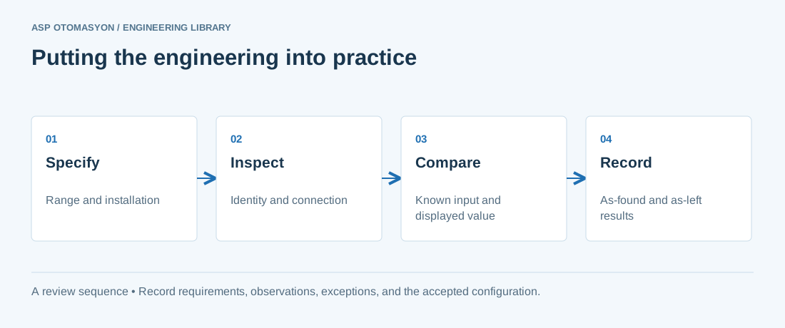
- Confirm the instrument tag, range, engineering unit, process connection, and environmental suitability against approved documents.
- Check the complete measurement chain, including sensor configuration, channel scaling, quality indication, and display units.
- Record reference equipment, uncertainty where relevant, test points, deviations, and the final configuration.
Follow an ASP project guide to connect the fundamentals with implementation and acceptance.
Primary references and further reading
Use the original specifications and product documentation for implementation details. The examples in this guide are illustrative engineering scenarios, not published project results.