
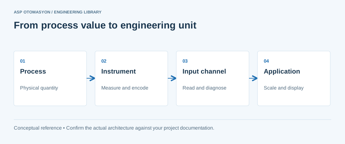
Temperature is the most commonly measured process variable in industrial automation, alongside pressure, level, and flow. Selecting the correct temperature sensor — and understanding its operating principle, accuracy class, and installation requirements — is essential for process control, quality assurance, and safety. The two dominant industrial temperature sensor technologies are Resistance Temperature Detectors (RTDs) and thermocouples (TCs).
Resistance Temperature Detectors (RTDs)
RTDs measure temperature by exploiting the predictable change in electrical resistance of a metal (typically platinum) as temperature changes. The relationship is defined by the Callendar–Van Dusen equation and is highly repeatable.
Pt100 — The Industrial Standard
The most common RTD is the Pt100 — a platinum element with a resistance of 100 Ω at 0 °C. Per IEC 60751, the temperature coefficient (α) is 0.00385 Ω/(Ω·°C), giving a sensitivity of approximately 0.385 Ω/°C. Pt1000 sensors (1,000 Ω at 0 °C) offer higher sensitivity and are used in applications with long cable runs.
RTD Element Types
| Type | Temperature Range | Accuracy | Characteristics |
|---|---|---|---|
| Thin-film | −50 to +500 °C (encapsulated to 600 °C) | Class A or B | Compact, cost-effective, good vibration resistance. Most common in industrial probes. |
| Wire-wound | −200 to +660 °C | Class A or B | Higher accuracy and stability over wide ranges. More fragile than thin-film. |
| Coiled (strain-free) | −200 to +850 °C | Class A | Best industrial stability. Wire expands freely, minimizing strain errors. |
| SPRT (Standard) | −200 to +500 °C | ±0.03 °C | Laboratory reference grade. Defines ITS-90. Not for industrial use. |
RTD Tolerance Classes (IEC 60751)
| Class | Tolerance Formula | At 0 °C | At 100 °C |
|---|---|---|---|
| AA | ±(0.1 + 0.0017|t|) | ±0.10 °C | ±0.27 °C |
| A | ±(0.15 + 0.002|t|) | ±0.15 °C | ±0.35 °C |
| B | ±(0.30 + 0.005|t|) | ±0.30 °C | ±0.80 °C |
| C | ±(0.60 + 0.01|t|) | ±0.60 °C | ±1.60 °C |
Wiring Configurations
- Two-wire — Simplest but includes lead wire resistance in measurement. Only suitable for non-critical applications.
- Three-wire — Industry standard. Uses a Wheatstone bridge to cancel lead resistance. Sufficient for most industrial applications.
- Four-wire — Highest accuracy. Separate current source and voltage measurement eliminates all lead resistance effects. Used for precision measurements.
Thermocouples
Thermocouples measure temperature using the Seebeck effect: when two dissimilar metals are joined at two junctions and a temperature difference exists between the junctions, a voltage (thermoelectric EMF) is generated. Thermocouples are self-powered (no external excitation needed) and cover a much wider temperature range than RTDs.
Common Thermocouple Types
| Type | Positive Leg | Negative Leg | Range (°C) | Sensitivity | Atmosphere |
|---|---|---|---|---|---|
| Type K | Chromel (Ni-Cr) | Alumel (Ni-Al) | −200 to +1,260 | ~41 µV/°C | Oxidizing, inert |
| Type J | Iron | Constantan (Cu-Ni) | −40 to +760 | ~55 µV/°C | Reducing, vacuum, inert |
| Type T | Copper | Constantan (Cu-Ni) | −200 to +370 | ~43 µV/°C | Oxidizing, reducing, vacuum |
| Type E | Chromel (Ni-Cr) | Constantan (Cu-Ni) | −200 to +870 | ~68 µV/°C | Oxidizing, inert |
| Type N | Nicrosil (Ni-Cr-Si) | Nisil (Ni-Si) | −200 to +1,260 | ~39 µV/°C | Oxidizing, inert (K alternative) |
| Type S | Pt-10%Rh | Pt | 0 to +1,480 | ~10 µV/°C | Oxidizing, inert |
| Type R | Pt-13%Rh | Pt | 0 to +1,480 | ~10 µV/°C | Oxidizing, inert |
| Type B | Pt-30%Rh | Pt-6%Rh | +200 to +1,700 | ~10 µV/°C | Oxidizing, inert |
RTD vs. Thermocouple Selection Guide
| Criterion | RTD (Pt100) | Thermocouple (Type K) |
|---|---|---|
| Temperature range | −200 to +850 °C | −200 to +1,260 °C (K), up to 1,700 °C (B) |
| Accuracy | ±0.1 to ±0.3 °C (Class A) | ±1.1 to ±2.2 °C (Standard) |
| Stability | Excellent (low drift) | Moderate (drift over time) |
| Response time | Slower (1–10 s) | Faster (0.1–5 s) |
| Signal level | Resistance (Ω) | Voltage (µV) |
| Cost | Higher | Lower |
| Cold junction | Not required | Required (CJC compensation) |
| Best for | −200 to +500 °C, high accuracy | >500 °C, fast response, cost-sensitive |
Installation Best Practices
- Thermowell installation — Always install sensors in thermowells for process-isolated removal. Thermowells must be rated for process pressure, velocity (vibration), and corrosion.
- Insertion depth — Minimum insertion depth should be 10× the sensor diameter into the process for accurate measurement. Center of the pipe is ideal for pipes > 300 mm diameter.
- Thermowell wake frequency — ASME PTC 19.3 TW calculates the maximum allowable insertion length based on process velocity to prevent thermowell failure from vortex-induced vibration.
- Cable routing — Route thermocouple and RTD extension cables away from power cables to avoid electromagnetic interference. Use shielded cable for RTDs in high-EMI environments.
- Transmitter location — Mount temperature transmitters close to the sensor to convert the low-level signal (Ω or µV) to 4–20 mA or digital (HART, Fieldbus) before long cable runs.
ASP OTOMASYON engineers select, configure, and commission temperature measurement systems for process industries across Turkey, ensuring accurate and reliable temperature control from sensor to control system.
Apply this to your project
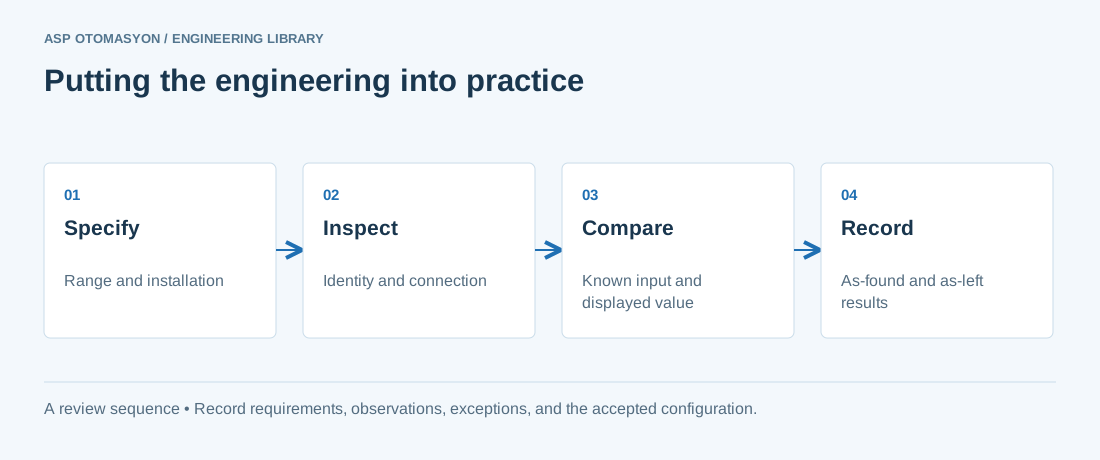
- Confirm the instrument tag, range, engineering unit, process connection, and environmental suitability against approved documents.
- Check the complete measurement chain, including sensor configuration, channel scaling, quality indication, and display units.
- Record reference equipment, uncertainty where relevant, test points, deviations, and the final configuration.
Follow an ASP project guide to connect the fundamentals with implementation and acceptance.
Primary references and further reading
Use the original specifications and product documentation for implementation details. The examples in this guide are illustrative engineering scenarios, not published project results.