
The quality of a control system's field wiring determines its reliability more than any other installation factor. Most "PLC faults" that appear in the first year of operation — intermittent inputs, noise-corrupted analog values, failing outputs — trace back to wiring decisions made in the panel: wrong return wiring, shared neutrals, missing shields, inadequate termination. This guide covers the wiring and termination practices that make I/O reliable for decades.
Input Wiring: Discrete
- Source vs sink — match the PLC input type to the sensor output: sourcing inputs (common +24 V) with sinking sensors (PNP), sinking inputs with NPN sensors. Mixing types silently reverses the logic — verify the module datasheet, not the habit.
- Return path discipline — each sensor's return goes to the same module's common; never daisy-chain commons across modules or panels where the currents can double back through other paths.
- Supply per group — power input groups (8 or 16 points) from a protected, labeled 24 V branch; a short on one field cable then only trips its own group instead of the whole rack.
- Inductive loads near inputs — contacts switching solenoids and contactors generate arcs; put the suppression (RC snubber or diode) on the load, keep input cables away from power cables, and use input filters or low-pass modules for slow signals.
- Status monitoring — use inputs that can distinguish open-circuit from closed-circuit where the state matters (e.g., safety-related position signals), or add diagnostics-capable modules.
Input Wiring: Analog
Analog signals (4–20 mA, RTD, thermocouple) are where wiring mistakes become process errors:
- Use shielded twisted-pair cable — twisted pair cancels magnetic coupling; the shield handles electric fields. Terminate the shield at one end (typically the panel) to the earth/ground bus; both-ends grounding creates ground loops.
- Keep analog cables away from power — at least 20–30 cm from power cables, more for VFD output cables; cross at 90° when crossing is unavoidable.
- 4–20 mA is preferred over voltage — current loops are immune to voltage drops over long runs; use 0–10 V only for short, in-panel distances.
- Loop-powered vs separately powered — know which the transmitter needs; a missing 24 V to a loop-powered transmitter produces a signal that looks like a real (low) value. Provide loop diagnostics (AI module with open-circuit detection) and monitor for it.
- RTD wiring — 3-wire RTDs cancel lead resistance only if all three wires have equal resistance and connect to the correct terminals; 4-wire is definitive for accuracy-critical measurements.
- Thermocouple wiring — the extension wire must be the same thermocouple type; a wrong-type extension wire creates a second junction with an uncontrolled temperature — one of the classic "mystery drift" causes.
Output Wiring
- Relay vs transistor outputs — relay for AC and mixed loads; transistor for DC high-frequency switching. Derate outputs for inductive loads (relay contact life is short with solenoids without suppression).
- Fusing — fuse each output group or, for critical loads, each output; a welded contactor coil that shorts will otherwise take out the module or the power supply.
- Feedback for safety-critical outputs — where an output energizes a hazard (motor starter, valve), read the device's actual state back (auxiliary contact) and interlock in logic; output transistors and relays fail in both directions.
- Output testing — provide a safe test mode (force with authorization) so commissioning can validate wiring without running the process.
Termination Practice
- Use proper ferrules on stranded wire for screw terminals; tinning stranded wire is not a substitute and cold-flows over time.
- Torque terminals to spec; re-torque after thermal cycling in the first months (loose terminals are the #1 intermittent fault).
- Leave slack and strain relief; wires subject to vibration (near doors, on hinged panels) need flexible routing and supports.
- Label everything: cables, cores, terminals, and field devices with the same identifiers as the drawings. The wiring is the documentation that survives.
- Keep spare cores terminated and labeled; the cost is trivial and the future change is free.
Verification Before Power-On
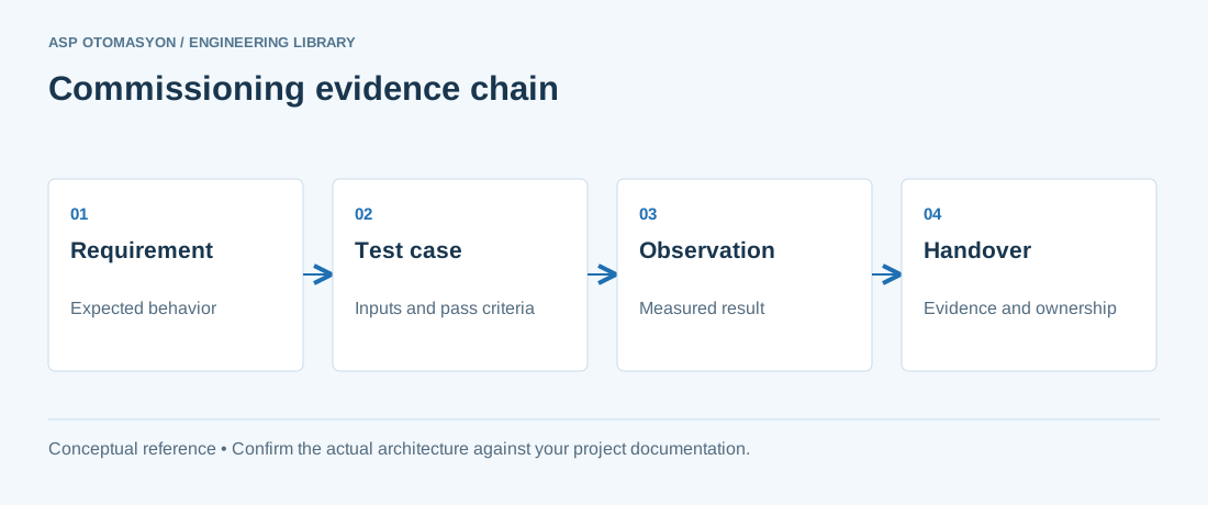
Before energizing, run a systematic check: continuity and insulation of every cable against the I/O list, polarity of every analog and supply point, no shorts between commons, and shield terminations correct. A full I/O check with the PLC in forced mode (each point toggled and verified at the field device) is the commissioning step that prevents 80% of startup defects — and it should be repeated after any panel modification.
Summary
Reliable I/O wiring is a set of decisions: source/sink matched, commons disciplined, analog shielded and routed away from power, RTD/TC wiring correct to the wire type, outputs fused and verified, and everything labeled. The wiring standard is a plant asset — write it down, enforce it in panel reviews, and verify with a full I/O check at commissioning. The field wiring is where control systems earn their reputation.
Apply this to your project
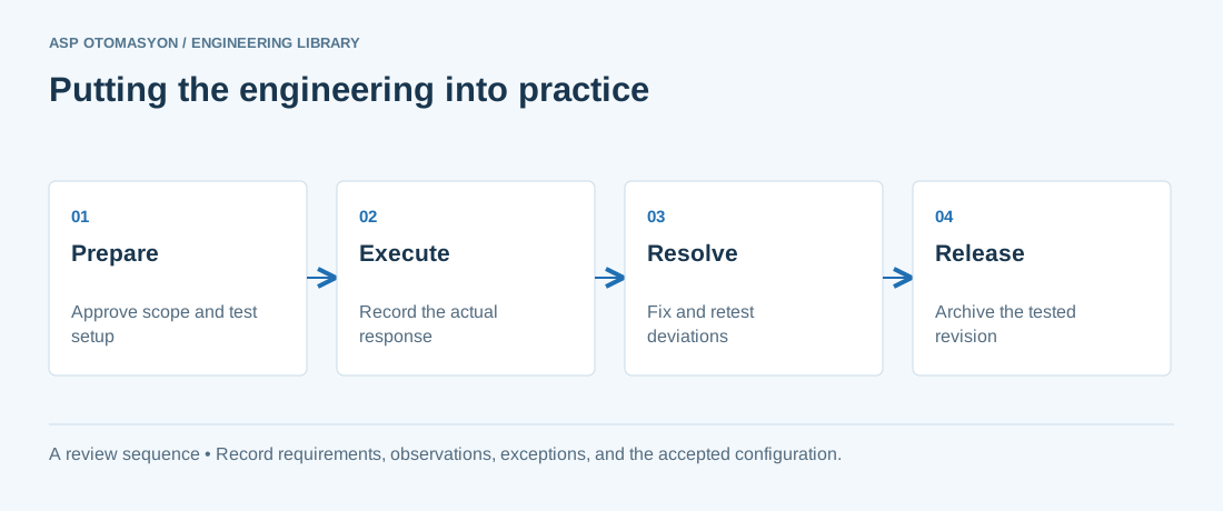
- Agree the test boundary and site authorization, especially where outputs or communications can affect operating equipment.
- Record expected and actual values, equipment identifiers, software revision, test conditions, and exceptions.
- Retest changed behavior and archive the final configuration with the test record and recovery instructions.
Follow an ASP project guide to connect the fundamentals with implementation and acceptance.
Primary references and further reading
Use the original specifications and product documentation for implementation details. The examples in this guide are illustrative engineering scenarios, not published project results.