
Modbus RTU over RS-485 remains the most widespread industrial fieldbus in the world: simple, open, and present in everything from energy meters to VFDs and legacy instruments. Its simplicity is also its trap — RS-485 is an electrical bus with strict physical rules, and most Modbus network failures (intermittent communication, corrupted data, one dead device killing the bus) are physical-layer problems, not protocol problems. This article covers the design and installation rules that make RS-485/Modbus RTU networks reliable.
How Modbus RTU Works
Modbus RTU is a master–slave protocol: one master polls each slave (addresses 1–247) with function codes (read/write coils and registers); the slave responds within a defined time. Frames are binary with a CRC-16 checksum. On RS-485, the bus is a single pair of wires carrying a differential signal — one talker at a time, so the protocol's timing and the bus's electrical behavior are inseparable: the master's turnaround time and the slaves' response windows are configured against the bus speed (baud rate) and distance.
The RS-485 Physical Rules
- Differential pair, twisted — A/B (or D+/D−) wires must be a twisted pair; the twist cancels interference. Belden-style 120 Ω cable is the standard.
- Termination — a 120 Ω resistor at each end of the bus (matching the cable's characteristic impedance). Missing terminations cause reflections that corrupt the signal; extra terminations in the middle load the bus. Termination is at the ends, not at the devices.
- Biasing — pull-up/pull-down resistors (often built into the master or a bias network) hold the line in the idle (mark) state so a disconnected bus reads as silence, not noise. A bus without bias produces garbage when all slaves are silent.
- Common reference — RS-485 is differential but still needs a common ground reference between devices (a third wire, or a common rail); floating devices with large potential differences damage transceivers — the classic "devices die slowly" failure.
- Topology — daisy-chain bus, not star: stubs (T-taps) must be short (under a few meters, less at high baud rates); long stubs are reflections. The bus is a line with the master at (or near) one end.
Network Design Decisions
| Parameter | Guidance |
|---|---|
| Baud rate | 9,600–19,200 bps for mixed/longer buses; 38,400–115,200 only for short, clean runs. Speed costs robustness; poll time is usually not the bottleneck. |
| Device count | 32 unit loads per segment (transceiver-dependent; repeaters extend); keep below ~20 devices for polling performance. |
| Distance | ~1,200 m at low baud; shorter at higher rates; beyond that, segment with repeaters or convert to fiber/Modbus TCP. |
| Polling strategy | Poll only what the application needs, at the needed rate; every extra register polled is bus time. Use block reads (function code 3/4 with register ranges) instead of single-register polls. |
| Slave response timeouts | Set the master's timeout above the slowest slave's worst-case response (including retries); too-short timeouts cause phantom failures on slow devices. |
Grounding and Wiring in Practice
Run the bus cable separate from power cables (20+ cm, cross at 90°), use shielded cable with the shield grounded at one end (the master end), and keep the bus out of VFD motor cable paths. In panels, route the RS-485 wires away from contactors and drives. For outdoor or long runs, consider RS-485 isolators (galvanic isolation) at the master and at exposed devices — isolation breaks the ground loops and the common-mode damage path.
Commissioning and Troubleshooting
- Test the bus before the devices — verify the master alone, then add slaves one at a time; a bus that fails when the third device joins is almost always a wiring/termination issue.
- Check the electrical values — measure A-B voltage (idle should be outside the ±200 mV deadband, typically −2 V to −6 V in the mark state) and the termination resistance (≈60 Ω on a properly terminated pair).
- Diagnose systematically — one bad slave (wrong address, faulty transceiver, shorted cable) can corrupt the whole bus; the isolation method (disconnect devices one by one) identifies it fast.
- Monitor the error counters — most masters/gateways count CRC errors and timeouts; a rising CRC error count is a physical-layer early warning (loose connection, termination drift, interference).
Summary
Modbus RTU over RS-485 works for decades when the physical layer is engineered: twisted-pair daisy-chain with 120 Ω termination at both ends, proper biasing, a common ground reference, short stubs, and clean routing away from power. Design the polling for the application's real needs, set timeouts honestly, and commission device by device. When Modbus "fails randomly," measure the bus — the protocol is not the problem, the physics is.
Apply this to your project
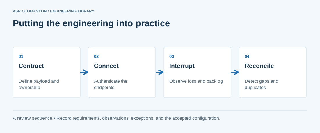
- Specify payload structure, units, identity, time semantics, access permissions, and protocol versions.
- Test backlog growth, connection loss, duplicate delivery, and restart behavior at the consuming application.
- Document how operators see failures and how the system distinguishes replayed data from current process state.
Follow an ASP project guide to connect the fundamentals with implementation and acceptance.
Primary references and further reading
Use the original specifications and product documentation for implementation details. The examples in this guide are illustrative engineering scenarios, not published project results.