
Every automated valve, damper, and gate needs an actuator — the muscle that moves the final element on command from the control system. The choice between pneumatic, electric, and (less often) hydraulic actuation is one of the most consequential decisions in an automation project: it determines the failure behavior, the energy needs, the maintenance, and the control quality for the life of the plant. This article covers the technologies, the selection criteria, and the engineering details that decide actuator success.
The Three Technologies
| Type | Principle | Strengths | Limitations |
|---|---|---|---|
| Pneumatic | Compressed air moves a diaphragm or piston against a spring | Fast, robust, simple, intrinsically safe, and fail-safe by spring (fail closed/open on air loss); the process industry default. | Needs instrument air; position holding requires air; less precise positioning without a positioner. |
| Electric | Electric motor (with gearbox) drives the stem | No air infrastructure, precise positioning (servo), energy efficient at hold, digital diagnostics. | Slower for large valves; fail-safe needs a spring module or battery (cost); power quality sensitivity. |
| Hydraulic | Hydraulic fluid powers a cylinder | Huge forces in small packages, precise, very stiff | Hydraulic infrastructure (pumps, oil, leaks); rare in general automation, standard in heavy applications (turbines, large gates). |
The process industry's default (pneumatic with fail-safe spring) exists because safety engineering demands a defined state on air failure — the actuator's failure mode is part of the valve's safety function (see the SIS article).
Selection Criteria
- Failure mode requirement — what must the valve do on power/air loss? Spring-return pneumatics and spring-module electrics provide fail-safe; the requirement comes from the process hazard analysis, not the vendor catalog.
- Force and speed — the required thrust/torque (from the valve's operating force — see the valve sizing article) and the stroke time (process and safety requirements); the actuator is sized with margin, never at the limit.
- Control duty vs on/off — modulating control needs a positioner (pneumatic) or servo control (electric) with the accuracy and response the loop needs; on/off service needs reliable end-stop operation.
- Environment — hazardous area (Ex rating — see the hazardous area article), temperature, outdoor exposure, and washdown; the actuator's enclosure and approvals must match.
- Energy infrastructure — is instrument air available and reliable? For remote or air-less sites, electric wins; for air-rich process plants, pneumatic remains economic.
- Diagnostics and integration — modern actuators (smart positioners, electric with fieldbus) report health, stroke counts, and travel; the integration (HART, fieldbus, or digital I/O) is selected with the plant's architecture.
Pneumatic Actuator Engineering Details
- Spring range and bench set — the actuator's spring and air range (e.g., 3–15 psi or 4–20 mA equivalents) are matched to the valve's force requirements; the bench set defines the fail position and the stroking behavior.
- Positioners — the modulating control package: the positioner converts the control signal into air pressure with position feedback (see the positioner article); a positioner without feedback is a guesser.
- Air quality — instrument air must be clean, dry, and oil-free (the plant's air system is part of the actuator's reliability — see the compressed air article); water in the air kills positioners quietly.
- Boosters and volume tanks — for fast stroking or fail-safe action on large valves, a volume booster or an air reservoir provides the instantaneous flow; the sizing is part of the safety calculation.
Electric Actuator Engineering Details
- Fail-safe options — spring-return modules, supercapacitor/battery backup, or fail-last; the chosen behavior is documented and tested (see the failure behavior testing in the FAT/SAT article).
- Duty and thermal — electric actuators are rated by duty cycle; a modulating service needs the continuous-duty rating, and the thermal environment derates the capability.
- Torque/limit switches and protection — the end-of-travel and torque limits are set at commissioning (jammed-valve protection); the setting and the test are commissioning records.
- Position feedback — analog (4–20 mA), digital (contacts), or bus-based (HART/fieldbus) feedback into the control system; the feedback is the operator's truth about the valve.
Summary
Actuator selection is decided by failure mode first, then force, speed, duty, environment, and infrastructure: pneumatic spring-return for the process default with safety implications, electric for precision and air-less sites, hydraulic for brute force. Size with margin, match the positioner/servo to the control duty, keep the air clean, and verify the fail behavior at commissioning. The actuator is the final element's muscle — the control system is only as good as the muscle it moves.
Apply this to your project
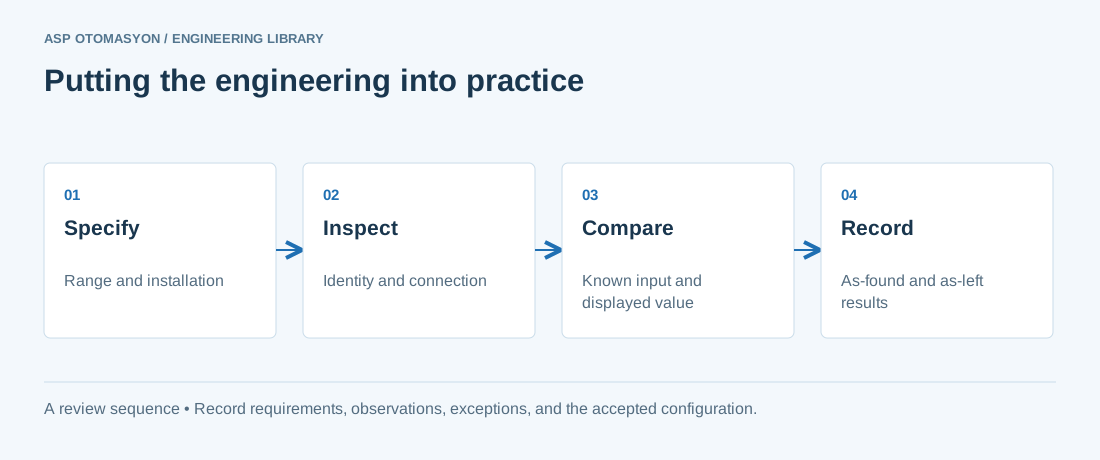
- Confirm the instrument tag, range, engineering unit, process connection, and environmental suitability against approved documents.
- Check the complete measurement chain, including sensor configuration, channel scaling, quality indication, and display units.
- Record reference equipment, uncertainty where relevant, test points, deviations, and the final configuration.
Follow an ASP project guide to connect the fundamentals with implementation and acceptance.
Primary references and further reading
Use the original specifications and product documentation for implementation details. The examples in this guide are illustrative engineering scenarios, not published project results.