
Control valve positioners are the final element of most control loops: they take the controller's command and position the valve accurately and repeatably. A valve without a positioner responds sluggishly and non-reproducibly; a well-tuned positioner makes the valve behave like the precise actuator the loop design assumes. This article covers positioner types, smart features, and the setup practices that keep final elements performing.
Why a Positioner?
Pneumatic actuators alone cannot position a valve precisely: friction, spring force, and process forces shift the actual position. The positioner closes the loop around the valve itself — it compares the commanded position (from the controller) with the actual stem position (measured internally) and adjusts the actuator air pressure until they match. The result:
- Accurate, repeatable positioning regardless of friction and process forces
- Faster response through air delivery tailored to the error
- Split-ranging and characterisation (see below) in a single device
- Diagnostics of the valve's health (with smart positioners)
Positioner Types
| Type | Signal | Notes |
|---|---|---|
| Pneumatic | 3–15 psi (0.2–1 bar) pneumatic signal | Legacy; used where no electrical signal is available or in hazardous areas without I/P converters |
| Electro-pneumatic (analog I/P) | 4–20 mA | The standard analog positioner; converts current to a pneumatic output |
| Smart (HART / FF / PA / digital) | 4–20 mA + digital (HART), or digital fieldbus (Foundation Fieldbus, PROFIBUS PA) | Digital calibration, diagnostics, and remote configuration; the modern standard |
Most new installations use smart positioners even on analog loops — the HART digital channel provides configuration and diagnostics without changing the 4–20 mA wiring.
Smart Positioner Features
- Auto-calibration: the positioner learns the valve's travel, stroke time, and friction by running an automatic stroke test at setup — no manual adjustments.
- Characterisation: the positioner can apply a flow characteristic (linear, equal percentage, or custom) electronically, so a linear valve can behave as equal-percentage where the loop needs it.
- Split range: two positioners can split a 4–20 mA range (e.g., 4–12 mA for one valve, 12–20 mA for another).
- Diagnostics: partial stroke testing (PST) for safety valves, travel deviation, friction trend, and cycle counting feed the maintenance program.
- Remote configuration: parameters, tuning, and calibration performed from the engineering tool or DCS — no climbing ladders with a screwdriver.
Positioner Tuning
Positioners have their own control parameters (gain, deadband, and speed settings) that must be tuned to the actuator:
- Too aggressive: the valve hunts or oscillates around the setpoint, wearing the stem and disturbing the process.
- Too soft: the valve responds sluggishly, adding dead time to the loop.
- Deadband: the positioner's deadband must be smaller than the control loop's sensitivity needs; excessive deadband causes limit cycling in the process.
Modern positioners auto-tune at commissioning; verify with a step test that the valve reaches position quickly without overshoot.
Installation and Setup Practices
- Mechanical mounting: the positioner must be rigidly mounted with the feedback linkage correctly connected and free of play; a loose linkage defeats everything else.
- Air supply: clean, dry, correctly regulated air (typically 4–7 bar depending on the actuator); moisture and oil are the enemies of pneumatic components.
- Calibration: run the auto-calibration (stroke, direction, zero/span) and verify the valve strokes fully in both directions.
- Characterisation: set the flow characteristic to match the loop design (equal percentage for most process control valves).
- Fail-safe direction: verify air-fail action (fail-open/fail-closed) matches the process safety requirement, and that the positioner's action is consistent.
- HART/network configuration: set the tag, units, and alarm levels; register the device in the asset database.
Maintenance and Diagnostics
- Trend friction and travel deviation: a gradual friction increase signals packing wear or contamination; travel deviation signals calibration drift or mechanical issues.
- Cycle counting: track valve cycles to schedule packing and component replacement.
- Partial stroke testing: for safety valves, PST exercises the valve without a full trip — a key diagnostic (ensure it is approved for the safety function's integrity).
- Air quality: maintain the filter/regulator; wet air ruins positioner performance and shortens life.
- Bench check on failure: when a valve misbehaves, test the positioner on the bench (or in bypass) to separate positioner fault from valve/actuator fault.
Common Pitfalls
- Unpowered HART diagnostics: a smart positioner whose diagnostics are never read is an expensive analog positioner.
- Wrong characterisation: an equal-percentage valve set to linear behaviour (or vice versa) makes the control loop unstable at one end of the range.
- Air supply neglect: most pneumatic faults trace back to wet or dirty air.
- Ignoring limit cycling: a constantly moving valve stem is a process-control symptom (usually tuning or deadband), not a valve personality trait.
- Bypassing PST: safety valves that are never exercised fail when needed; use the positioner's PST capability within the safety process.
Summary
Control valve positioners make the final element precise: accurate positioning, characterisation, split-ranging, and — with smart devices — diagnostics and remote setup. Mount and calibrate them properly, tune them to the actuator, keep the air clean, and use the diagnostics to run the valve predictively. The loop can only be as good as its final element, and the positioner is what makes the final element good.
Apply this to your project
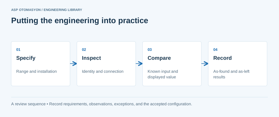
- Confirm the instrument tag, range, engineering unit, process connection, and environmental suitability against approved documents.
- Check the complete measurement chain, including sensor configuration, channel scaling, quality indication, and display units.
- Record reference equipment, uncertainty where relevant, test points, deviations, and the final configuration.
Follow an ASP project guide to connect the fundamentals with implementation and acceptance.
Primary references and further reading
Use the original specifications and product documentation for implementation details. The examples in this guide are illustrative engineering scenarios, not published project results.