
IO-Link (IEC 61131-9) is the standard for communicating with smart sensors and actuators at the field level. It replaces the traditional "switch or analog wire" with a point-to-point digital link between each device and its IO-Link master, carrying not just the process value but also device identity, diagnostics, configuration, and events. IO-Link is not a fieldbus that replaces PROFINET or EtherNet/IP — it sits below them, connecting the last meter between the field device and the network.
How IO-Link Works
- Point-to-point: each IO-Link device connects to one IO-Link master port with a standard 3-wire cable (L+/L-/C/Q) — the same 3-wire unshielded cable used for conventional sensors, so no special cabling is required.
- Communication modes: SIO (standard I/O, where the port behaves like a normal sensor input) and IO-Link communication at 4.8, 38.4, or 230.4 kbit/s (COM1/COM2/COM3).
- Master: the IO-Link master manages the ports, exchanges data with the higher-level network (PROFINET, EtherNet/IP, EtherCAT, OPC UA), and forwards the devices' parameters and diagnostics.
- Data types: each cycle transfers process data (the measured value or status), plus on-request ISDU (Indexed Service Data Unit) parameters and event messages.
What IO-Link Delivers
| Capability | What it means on the plant floor |
|---|---|
| Device identity (IODD) | The master reads vendor, model, and serial number automatically — no manual configuration |
| Diagnostics | Device health, contamination warnings, and failure events reach the controller/HMI |
| Parameterization | Sensor settings (e.g., switch points, output logic) are stored and downloaded automatically on device replacement |
| Extended data | Multiple process values per device (e.g., distance + quality), plus on-device data storage |
| Automatic device replacement | A failed sensor is swapped and the master re-programs the new unit from stored parameters — no manual setup |
The IODD (IO Device Description) file is the device's electronic data sheet; engineering tools use it to configure masters and to map device data into the PLC tag structure.
Why It Matters for Maintenance
IO-Link's biggest operational payoff is diagnostics and replacement:
- Instead of a binary "sensor works / sensor failed", the controller sees contamination warnings, temperature, and operation counts — enabling condition-based maintenance.
- Device replacement drops from a configuration task to a physical swap; the master restores parameters automatically. This reduces downtime and removes a class of human error.
- Faults are localized: the master port and device communicate health status, so technicians know exactly which device failed.
Integration Architecture
Field devices (sensors, actuators, valves, RFID)  ← IO-Link 3-wire
        │
        ▼
IO-Link masters (per cabinet / machine)
        │  PROFINET / EtherNet/IP / EtherCAT / OPC UA
        ▼
PLC / SCADA / historian
- Masters come in modular (IP20, in-cabinet) and field (IP65/67, machine-mounted) forms; field masters save cabling on machines.
- The PLC sees each device as a normal I/O block — process data as inputs/outputs, parameters via the vendor's function blocks or the network tool.
- Data can flow onward to SCADA and historians via OPC UA, giving the diagnostics and parameters to the maintenance systems (see the OPC UA information model article).
Selection and Design Considerations
- Device ecosystem: IO-Link has broad vendor support — proximity sensors, photoelectrics, valves, motor starters, RFID, pressure/temperature transmitters, and more. Verify the IODD availability and quality for each device type.
- Cable length: IO-Link is specified for up to 20 m of standard 3-wire cable — plenty for machine-level wiring.
- Port planning: count ports carefully; masters support 4, 8, or 16 ports per unit, and some ports can be configured as standard digital I/O.
- Engineering tooling: plan how IODDs and parameter sets are managed — in the vendor's tool, in the PLC engineering system, or in a central asset database.
- Backup of parameter data: store device parameter sets (or enable on-device data storage) so replacements are truly plug-and-play.
Common Pitfalls
- Wiring mistakes: IO-Link uses standard sensor cables, but polarity and pin assignment still matter; a mis-wired port falls back to SIO or fails.
- Ignoring diagnostics: the whole value of IO-Link is the data — if the diagnostics are not mapped into the HMI/SCADA, it is just an expensive switch.
- Mixed-mode confusion: a port in SIO mode behaves like a plain input; configuring it as IO-Link when the device is not IO-Link (or vice versa) causes mysterious failures.
- No parameter backup: without stored parameters or on-device storage, the "plug-and-play replacement" promise evaporates.
Summary
IO-Link brings plug-and-play intelligence to the last meter of the automation network: automatic identity, parameterization, diagnostics, and seamless device replacement over standard 3-wire cabling. It complements — rather than replaces — the higher-level fieldbuses, and it pays off most in maintenance: faster fault finding, condition-based care, and zero-configuration sensor swaps. For new machines and retrofit sensor fleets, it is a low-risk, high-return upgrade.
Apply this to your project
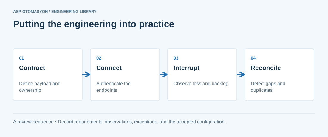
- Specify payload structure, units, identity, time semantics, access permissions, and protocol versions.
- Test backlog growth, connection loss, duplicate delivery, and restart behavior at the consuming application.
- Document how operators see failures and how the system distinguishes replayed data from current process state.
Follow an ASP project guide to connect the fundamentals with implementation and acceptance.
Primary references and further reading
Use the original specifications and product documentation for implementation details. The examples in this guide are illustrative engineering scenarios, not published project results.