
The OPC UA information model is what makes OPC UA far more than a data transport. Where OPC Classic moved flat tag lists, OPC UA describes the structure and meaning of data: objects, their properties, their relationships, and the operations that can be performed on them. A well-designed information model is the difference between a client that must guess what a tag means and a client that can explore, interpret, and automate against the server's data. This article explains the core concepts and a practical design process for building your own UA information model.
Core Building Blocks
Every UA address space is built from nodes connected by references.
| Node class | Purpose | Example |
|---|---|---|
| Object | Represents a physical or logical entity | a pump, a line, a tank |
| Variable | Holds a value with data type, quality, timestamp | pump speed, tank level, line status |
| Method | An invocable operation with input/output arguments | start pump, reset alarm |
| ObjectType | Template defining the structure of objects | PumpType with variables and methods |
| VariableType | Template for variables (incl. data type and units) | AnalogItemType (EU range, engineering units) |
| DataType | Defines structured data types | DiagnosticStatus (struct) |
| View | A filtered subset of the address space | "Operators", "Maintenance" |
References connect nodes and are typed: Organizes (hierarchy), HasComponent (part-of), HasProperty, HasSubtype (type inheritance), and HasEventSource, among others. The address space is a graph, not a tree — the same node can be referenced from several places.
Start from the Standards
Before designing from scratch, check whether a companion specification already covers your domain. Companion specs define standardized information models for industries and applications, and using them gives instant interoperability with existing clients:
- OPC 10000-100 — devices (field devices, general device model)
- OPC UA for PLCopen — mapping IEC 61131-3 data into UA
- OPC UA for ISA-95 / MES — job orders, equipment, materials
- OPC UA for Analytics, Machine Vision, PackML (PackML companion), DI (device integration)
- Industry-specific ones: energy (OPC UA for Energy), robotics (OPC UA for Robotics), CNC (Umati / OPC UA for MachineTools)
If a companion spec fits, adopt it — even partially. If not, design your own model but reuse the standard base types (BaseObjectType, BaseVariableType, AnalogItemType) so that generic UA clients can still browse and interpret your data.
Design Process
1. Define the purpose and audience
Who will consume this model? Operators need status and commands; maintenance needs diagnostics and run hours; MES/ERP needs production counts and state; analytics needs trends and quality. Different audiences may be served by different views over the same underlying nodes.
2. Identify the objects
List the physical and logical entities: machines, process units, lines, tanks, drives, sensors. Choose names that match the plant's own terminology — the model should read like the plant layout, not like a tag dump.
3. Define types, then instantiate
For each object family, create an ObjectType with its variables and methods. For example, a PumpType might contain:
- Variables: Speed (AnalogItemType, RPM), Running (Boolean), Current (AnalogItemType, A), RunHours (AnalogItemType, h)
- Methods: Start(), Stop(), ResetFault()
- Properties: SerialNumber, Model, InstallationDate
Then instantiate objects (Pump_1, Pump_2) as instances of the type. Instances inherit the type's structure, so clients that understand the type can process every instance uniformly.
4. Choose data types carefully
Use the right scalar types (Float vs. Double), and define structures for composite values instead of flattening them into many tags. Add engineering units (via AnalogItemType) so clients can display and convert correctly. For status, prefer structured status variables over cryptic integer codes.
5. Model relationships
Connect objects with meaningful references: a tank FeedsTo a pump; a line Contains machines; alarms BelongTo their source object. This graph is what makes the model browsable and analyzable.
6. Plan for events and alarms
If the system generates alarms, model them as UA events (per OPC UA Part 9 / 18) attached to their source objects, rather than as Boolean tags. Clients can then subscribe to event notifications with filtering, and the alarm history is structured.
7. Version and document
Information models evolve. Keep a version number on the model root, document naming rules, and follow the same change-control discipline as software: a client written against v1 of the model must not break when v2 adds nodes.
Practical Example: a Simple Line Model
Line_1 (Object, LineType)
├── Speed (AnalogItemType, m/min)
├── State (Variable, LineState enum)
├── TotalCount (Variable, UInt32)
├── RejectCount (Variable, UInt32)
├── Machines (Organizes)
│   ├── Filler_1 (FillerType)
│   │   ├── Running (Boolean)
│   │   ├── Level (AnalogItemType, %)
│   │   └── Start() / Stop()
│   └── Capper_1 (CapperType)
│       ├── Torque (AnalogItemType, Nm)
│       └── FaultCode (Variable, UInt16)
└── Alarms (Organizes)
    ├── LineStopped (Event)
    └── RejectRateHigh (Event)
This model lets a generic UA client browse to Line_1, see its machines and their capabilities, invoke Start/Stop, and subscribe to alarms — all without prior knowledge of the vendor's tag naming.
Summary
An OPC UA information model is the contract between your automation layer and every consumer of its data. Reuse companion specs where they exist, define clear types with proper units and structures, connect objects with meaningful references, model alarms as events, and version the model like software. The result is an address space that is self-describing, easier to integrate, and dramatically cheaper to maintain than a flat tag list.
Apply this to your project
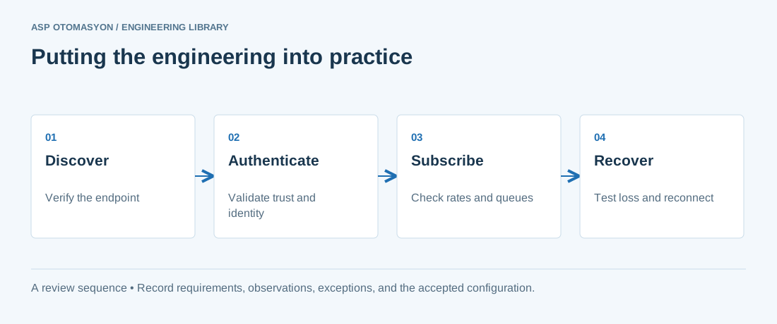
- Record the endpoint, supported security policies, application identity, certificate expiry, and user permissions.
- Verify the value, engineering unit, StatusCode, and source timestamp together at the receiving application.
- Test disconnection and recovery with representative subscriptions; preserve evidence of any data gaps or repeated values.
Follow an ASP project guide to connect the fundamentals with implementation and acceptance.
Primary references and further reading
Use the original specifications and product documentation for implementation details. The examples in this guide are illustrative engineering scenarios, not published project results.