
In industrial electrical systems, power factor is the ratio of real power (performing useful work) to apparent power (flowing in the circuit). A low power factor means the facility draws more current than necessary for the same amount of useful power, increasing losses, utility charges, and equipment stress. Power factor correction (PFC) and harmonics mitigation are essential engineering practices for efficient industrial energy management.
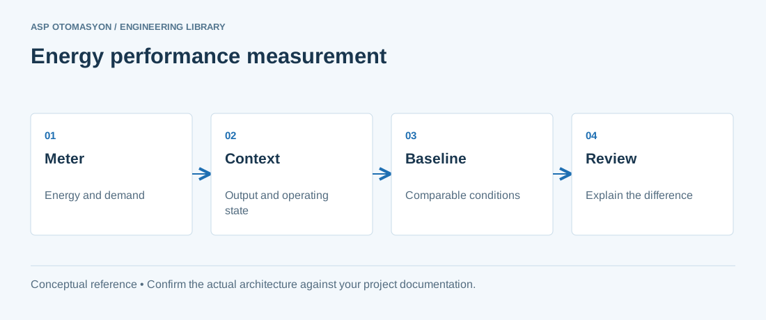
Understanding Power Factor
Power factor has two components in modern industrial systems:
- Displacement power factor — Caused by phase shift between voltage and current in inductive loads (motors, transformers, reactors). Corrected with capacitor banks.
- Distortion power factor — Caused by harmonic currents drawn by non-linear loads (VFDs, rectifiers, arc furnaces, UPS systems). Corrected with harmonic filters.
The true power factor is the product of displacement and distortion power factors:
True PF = cos(φ) × [I₁ / Iᵣₘₛ] = cos(φ) / √(1 + THDᵢ²)Where cos(φ) is the displacement factor, I₁ is the fundamental current, Iᵣₘₛ is the total RMS current, and THDᵢ is the total harmonic distortion of the current.
Why Power Factor Matters
| Impact | Description |
|---|---|
| Utility penalties | Most utilities charge industrial customers a penalty when power factor falls below 0.90–0.95. Penalties can add 5–15% to the electricity bill. |
| Increased losses | Line losses are proportional to I²R. A PF of 0.7 means twice the current (and four times the losses) compared to PF 1.0 for the same real power. |
| Reduced capacity | Transformers, cables, and switchgear are rated in kVA. Low PF consumes capacity that could serve additional loads. |
| Voltage drop | Higher current increases voltage drop along distribution cables, potentially affecting sensitive equipment. |
Power Factor Correction Methods
Fixed Capacitor Banks
Individual capacitors connected to large motors or fixed loads. Simple and economical for stable, continuous loads. Risk of over-correction (leading PF) during light load conditions.
Automatic Capacitor Banks (Switched)
Multi-step capacitor banks controlled by a power factor regulator that measures the system PF and switches capacitor steps in and out to maintain a target PF (typically 0.95–0.98 lagging). Each step is typically 25–100 kVAr. Switching is done via dedicated capacitor contactors with damping resistors to limit inrush current.
Active Power Factor Correction (Active Front End)
Power electronic converters (IGBT-based) that shape the input current to be sinusoidal and in phase with the voltage. Used in modern VFDs and UPS systems. Achieves PF > 0.99 and THDᵢ < 5%. Also enables regenerative operation (returning energy to the grid).
Harmonics in Industrial Systems
Harmonics are integer multiples of the fundamental frequency (50 Hz in Turkey) caused by non-linear loads. The most significant harmonic sources in industrial facilities are:
- Variable frequency drives (VFDs) — Six-pulse rectifiers generate 5th, 7th, 11th, 13th harmonics.
- Arc furnaces — Broad-spectrum harmonic generation with interharmonics.
- Switch-mode power supplies — IT equipment, LED drivers, UPS systems.
- Saturated transformers — Overexcitation generates odd harmonics.
Harmonic Mitigation Techniques
| Technique | Description | Effectiveness |
|---|---|---|
| Passive filters | Tuned LC circuits (capacitor + reactor) connected in parallel, tuned to specific harmonic frequencies (e.g., 250 Hz for 5th harmonic). | Reduces targeted harmonics to acceptable levels. Risk of resonance with the network. |
| Active filters | Power electronic devices that measure harmonic currents and inject equal-but-opposite currents in real time. | Mitigates all harmonics up to the 50th. Handles dynamic load changes. Higher cost. |
| Hybrid filters | Combination of passive and active filters. Passive handles bulk harmonics; active handles residual and dynamic components. | Cost-effective for large installations with both steady and varying harmonic loads. |
| Multi-pulse rectifiers | 12-pulse, 18-pulse, or 24-pulse rectifier configurations using phase-shifting transformers. | Eliminates lower-order harmonics at the source. Common in large VFDs. |
| Active front end (AFE) | IGBT-based rectifier replacing the diode bridge in VFDs. | THDᵢ < 5%, near-unity PF, regenerative capability. |
Standards and Limits
- IEEE 519 — Recommended practice for harmonic control in electrical power systems. Limits voltage THD to 5% and individual harmonic voltages to 3% at the point of common coupling (PCC).
- IEC 61000-3-6 — Assessment of emission limits for distorting loads in MV and HV power systems.
- EN 50160 — Voltage characteristics of electricity supplied by public distribution systems (European standard).
- Turkish Electricity Distribution Standard — Requires industrial customers to maintain PF ≥ 0.90 (inductive) and comply with harmonic emission limits.
ASP OTOMASYON conducts power quality audits, harmonic analysis, and designs power factor correction and harmonic mitigation solutions for industrial facilities across Turkey, helping clients reduce utility penalties and improve electrical system reliability.
Apply this to your project
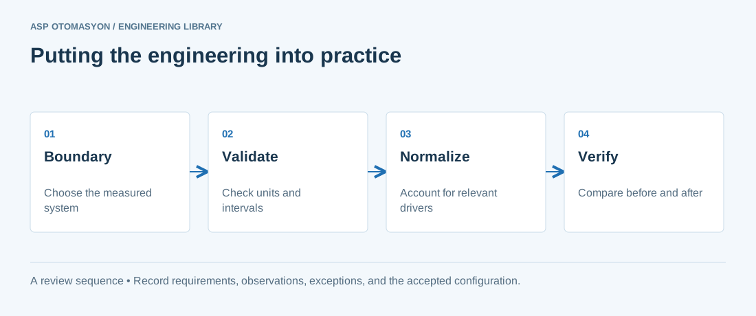
- Define the measurement boundary, meter ratios, units, time interval, and treatment of missing or reset readings.
- Capture production quantity, operating hours, and other relevant drivers alongside energy use.
- State the baseline and normalization assumptions when reporting a change; separate measured results from estimates.
Follow an ASP project guide to connect the fundamentals with implementation and acceptance.
Primary references and further reading
Use the original specifications and product documentation for implementation details. The examples in this guide are illustrative engineering scenarios, not published project results.