
The control valve is the final element of most process loops — and a valve sized wrong is a loop that cannot perform: an oversized valve operates at 5% opening where every stick-slip becomes a process bump; an undersized valve cannot deliver the required flow at maximum demand. Control valve sizing is the calculation of the valve's flow coefficient (Cv) from the process conditions, and the selection of the trim and characteristics that make the loop controllable across its whole range.
The Flow Coefficient Cv
Cv is the valve's capacity: the number of US gallons per minute of water at 60 °F that flow through the fully open valve with a 1 psi pressure drop. The sizing calculation determines the required Cv at the design conditions:
- Liquid service — Cv = Q × √(SG / ΔP) for non-choked flow (Q in gpm, SG specific gravity, ΔP pressure drop), with the choked-flow correction for flashing and cavitating conditions.
- Gas/steam service — the compressible flow equations (per IEC 60534-2-1 / ISA-75.01) with the expansion factor Y and the pressure-drop ratio limits; gas sizing is a published formula set, not a rule of thumb.
- Units discipline — the formulas are unit-sensitive; the standard tables and the vendor sizing software handle the conversions — the engineer's job is the inputs.
The inputs are the real engineering: maximum, normal, and minimum flow; the upstream and downstream pressures at each condition (including the pump/compressor curve behavior); the fluid properties (density, viscosity, vapor pressure, compressibility); and the line size and piping geometry.
The Sizing Margins
A valve is sized for a range, not a point:
- Maximum flow — typically 110–125% of the maximum expected flow (the design margin); the valve must deliver it with the available pressure drop.
- Normal flow — the operating point should fall in the valve's best control range: 10–80% of travel for a globe valve (the classic guidance), with the characteristic chosen so the loop gain is reasonably constant at the operating region.
- Turndown — the ratio of maximum to minimum controllable flow; rangeability (the trim's ratio, e.g., 50:1) and the characteristic decide whether the valve controls the small flows too. A valve that can only throttle from 100% to 40% makes the plant bypass it.
- Pressure drop allocation — the valve needs a real share of the system's pressure drop at design flow (typically 25–50% of the circuit drop, more where tight control matters); a valve with almost no drop across it has almost no authority — the classic "valve too big for the circuit" failure.
Flow Characteristics
The valve's installed characteristic (flow vs travel) is chosen to compensate the loop's process gain:
- Linear — flow proportional to travel; for loops where the process gain is constant (level loops, some flow loops).
- Equal percentage — small flow changes at low travel, large at high travel; for loops where the process gain falls with load (pressure and temperature loops, most process control) — the common default.
- Quick opening — large flow change at small travel; for on/off and relief duties, not for modulating control.
The installed characteristic differs from the inherent (bench) characteristic because of the piping and the pressure drop distribution — the sizing engineer checks the installed behavior, not just the catalog curve.
Special Services
- Cavitation and flashing — liquid services near vapor pressure need anti-cavitation trims or special valve designs; cavitation destroys trim and sounds like gravel in the pipe.
- Noise — high-pressure-drop gas services generate noise; the sizing calculation includes the noise prediction (IEC 60534-8-3), and the design may need low-noise trims, silencers, or line-size increases.
- Erosive and slurry services — materials, trim geometry, and velocities are selected for the wear mechanism; the sizing software's standard results do not cover erosion — the application engineering does.
- Safety valves (SIS duty) — the final element of a safety function is sized per the safety requirements (leakage class, stroke time, fail position) — see the SIS article; the process sizing is only half of that selection.
Summary
Control valve sizing is the Cv calculation from real process conditions (flow, pressures, fluid properties) with honest margins, followed by the selection of characteristic, trim, and special-service features that make the loop controllable across its range. Size for the range, allocate the pressure drop, respect the installed characteristic, and account for cavitation, noise, and erosion where they apply. The valve is the loop's final element — a correctly sized one is invisible, a mis-sized one is the loop's constant complaint.
Apply this to your project
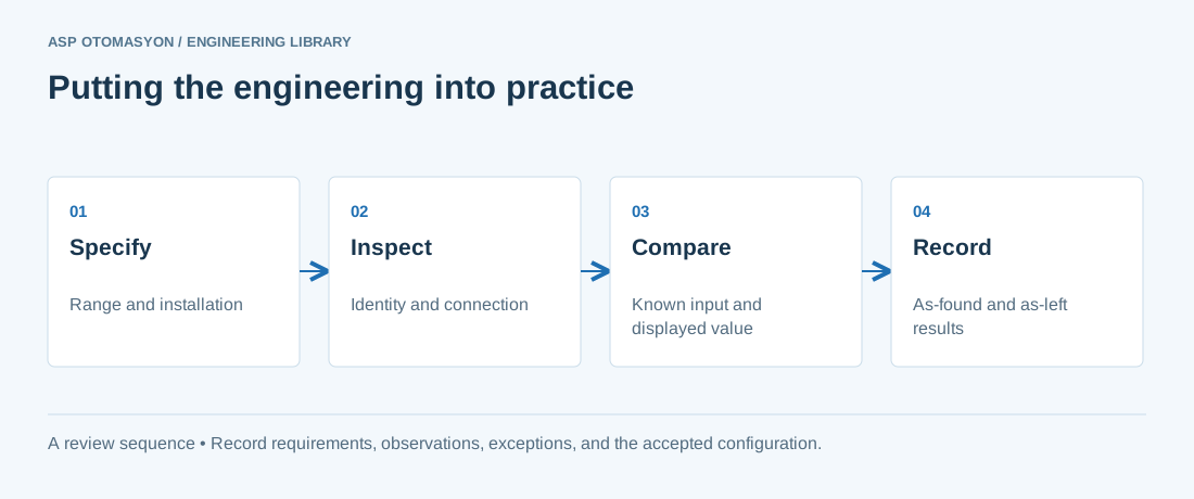
- Confirm the instrument tag, range, engineering unit, process connection, and environmental suitability against approved documents.
- Check the complete measurement chain, including sensor configuration, channel scaling, quality indication, and display units.
- Record reference equipment, uncertainty where relevant, test points, deviations, and the final configuration.
Follow an ASP project guide to connect the fundamentals with implementation and acceptance.
Primary references and further reading
Use the original specifications and product documentation for implementation details. The examples in this guide are illustrative engineering scenarios, not published project results.