
An analog loop check confirms that a known input produces the expected value and diagnostic behavior through the measurement chain. It is different from calibrating a sensor or proving the process measurement under operating conditions. Keep these activities separate in the test record so that a passing display check is not mistaken for complete instrument validation.
Design the requirement before the configuration
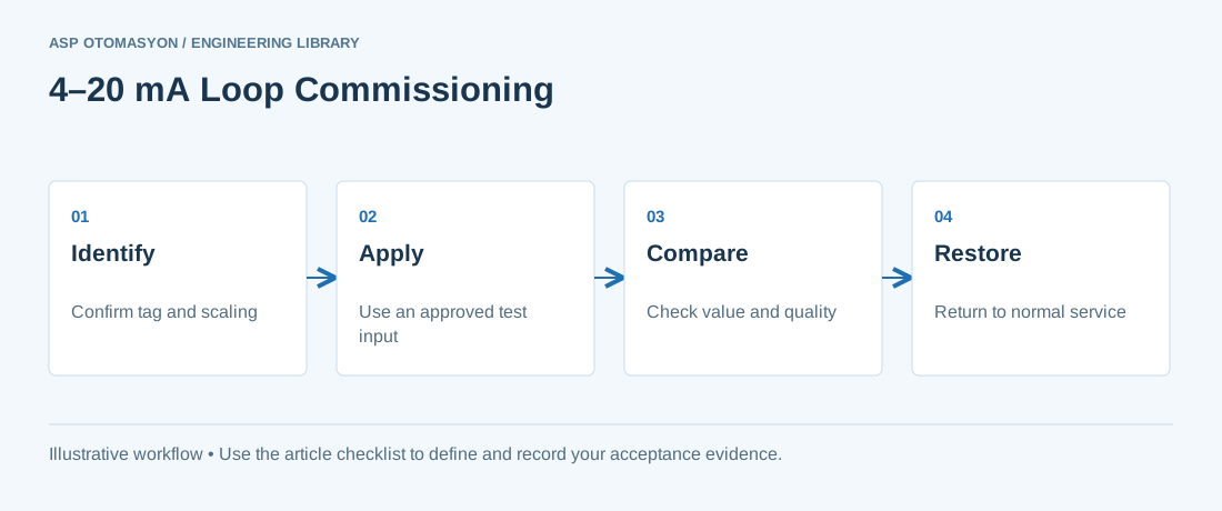
Before testing, confirm the approved tag, instrument range, channel type, scaling location, and display unit. Identify whether the signal is sourced or simulated at each point and agree safe test conditions with the responsible site personnel. Avoid applying an output to a live control function without an approved test method. Follow instrument documentation for power, wiring, isolation, and test equipment connections; do not infer them from the nominal current range.
Worked scenario
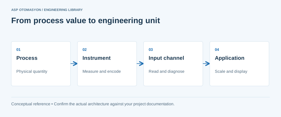
For an illustrative linear 0–10 bar measurement represented by 4–20 mA, 4 mA corresponds to 0 bar, 12 mA to 5 bar, and 20 mA to 10 bar. The formula is value = lower range + (current − 4) / 16 × span. A square-root flow application or a different transmitter configuration needs different treatment. Confirm where any transformation occurs to avoid applying it twice.
What to verify
| Check | Evidence to record |
|---|---|
| Identity | Tag, channel, transmitter range, and display unit agree |
| Test points | Record input and displayed result at agreed points |
| Diagnostics | Confirm specified under-range, over-range, and failure indications |
| Restoration | Remove test mode and confirm normal service under site procedure |
Acceptance and handover
Record as-found and as-left results, the reference instrument, test conditions, acceptance tolerance, and any configuration change. If the display is correct but source diagnostics are lost, the loop is not fully proven. Resolve and retest discrepancies before closing the record.
Continue the engineering work
Use the related technical library for deeper background, or follow an ASP project guide to plan the implementation sequence.
Primary references and further reading
Use the original specifications and product documentation for implementation details. The examples in this guide are illustrative engineering scenarios, not published project results.