
Instrument loop diagrams (loop sheets) are the detailed engineering drawings that show exactly how a single instrument or control loop is wired, connected, and powered. While a P&ID shows the process and its instruments symbolically, the loop drawing shows the physical reality: which terminal on the transmitter goes to which terminal on the marshalling cabinet, the signal type, the power supply, the cable number, and the instrument tag. Loop diagrams are the essential documentation for installation, commissioning, troubleshooting, and maintenance of every measurement and control loop.
Loop Diagram vs. P&ID
| Document | Shows | Used by |
|---|---|---|
| P&ID | Process equipment, piping, and instrument symbols; control philosophy | Process and systems engineers |
| Loop diagram | Physical wiring, terminals, signal types, power, cable numbers, instrument connections | I&C engineers, electricians, technicians |
| Hook-up / installation detail | Physical mounting, impulse lines, manifolds, brackets | Installation crews |
In a well-run project, the P&ID defines what the loop does, the loop diagram defines how it is built, and the hook-up drawing defines where and how it is mounted.
What a Loop Diagram Contains
- Instrument tag (per ISA-5.1/ISA-TR20 functional identification, e.g., PT-101, TIC-202) and the loop number
- Field instrument: transmitter, sensor, valve positioner, switch, analyzer — with its terminals
- Signal type: 4–20 mA (2-wire or 4-wire), HART, digital fieldbus (Foundation Fieldbus, PROFIBUS PA), discrete (dry contact, 24 V DC), thermocouple, RTD
- Marshalling/junction boxes: terminal numbers at each junction
- I/O card: the DCS/PLC input or output channel (e.g., AI-05, DO-12) and its terminal assignment
- Power: loop power source (24 V DC, 230 V AC where applicable), fuse/breaker references
- Cables: cable numbers, types, and pair/wire assignments
- Grounding and shields: shield termination practice (one end grounded, usually at marshalling or I/O)
- Function block references: the DCS faceplate/tag, and for control loops the controller and final element
- Notes and references: range, calibration units, special conditions
Standard Symbols and Identification
Instrumentation symbols follow ISA-5.1 (IEC 62424 is the process-flow-diagram counterpart; many projects also use ISA-TR20 for instrument identification). The tag structure is:
Example:   PT-101-A  or  TIC-202
            │  │  └─ loop/unit number
            │  └──── function (T=temperature, P=pressure, L=level, F=flow, A=analysis...)
            └─────── type (I=indicator, C=controller, T=transmitter, S=switch...)
Signal line conventions on loop sheets:
- Solid line — analog signal (4–20 mA, HART)
- Dashed line — digital/binary signal or pneumatic signal
- Slash marks on a line — number of cores/wires in the cable
- Circle symbols — instrument location: field-mounted (no line), panel-mounted (line across), etc.
Creating Good Loop Documentation
- One sheet per loop. Keep the drawing readable; split complex loops (e.g., a cascade with multiple transmitters) into related sheets with clear cross-references.
- Use consistent templates. Standardized borders, title blocks, and symbol libraries make sheets comparable across the project.
- Include the control scheme. For control loops, show the controller, its inputs, and the final element so the sheet tells the complete story.
- Reference the tag database. The loop sheet, the I/O list, and the DCS tag configuration must agree — discrepancies are a leading cause of commissioning errors.
- Version control. Loop sheets change when instruments are replaced or wiring changes; track revisions and mark as-built status.
Using Loop Diagrams in Troubleshooting
When a loop fails, the loop diagram is the fastest route to the fault:
- Identify the instrument tag from the HMI or alarm.
- Open the loop sheet: it lists the signal type, the cable, the terminals, and the I/O channel.
- Measure at the defined test points (e.g., at the marshalling terminal, simulate the 4–20 mA signal) to isolate field vs. cabinet vs. I/O card.
- Check the power and fuse references before suspecting the instrument.
- Document the fix and mark the loop sheet as-built if wiring changed.
Common Documentation Defects to Avoid
- Missing or wrong terminal numbers — the most frequent source of wiring errors; verify against as-built.
- Unclear shield/ground practice — ground loops and noise problems often trace back to shields grounded at both ends.
- Outdated sheets — instruments replaced without updating the drawing create dangerous ambiguity.
- Inconsistent tags — the same loop named differently on the P&ID, the I/O list, and the loop sheet.
- No revision history — technicians cannot tell which version of the sheet applies to the installed loop.
Summary
Loop diagrams are the wiring-level documentation that makes an instrumented plant installable, commissionable, and maintainable. Keep them accurate, complete, and under version control; standardize symbols and tags; and treat them as living documents that must be updated whenever the physical loop changes. In troubleshooting, a good loop sheet can cut fault-finding time from hours to minutes.
Apply this to your project
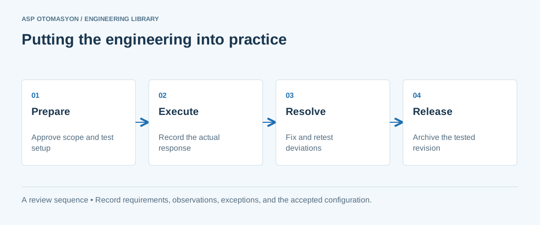
- Agree the test boundary and site authorization, especially where outputs or communications can affect operating equipment.
- Record expected and actual values, equipment identifiers, software revision, test conditions, and exceptions.
- Retest changed behavior and archive the final configuration with the test record and recovery instructions.
Follow an ASP project guide to connect the fundamentals with implementation and acceptance.
Primary references and further reading
Use the original specifications and product documentation for implementation details. The examples in this guide are illustrative engineering scenarios, not published project results.