
Sequential Function Chart (SFC) is the IEC 61131-3 programming language designed for state-based, sequential control. Where ladder logic excels at combinational and interlock logic, SFC structures a program as a sequence of steps and transitions — the same mental model an engineer uses when writing a process description: wait for a condition, then do the next action. SFC is the standard choice for batch processes, machine sequences, recipe-driven production, and any application with clearly defined phases.
The SFC Model
An SFC program is built from four element types:
- Steps — each step represents a state of the process and contains one or more actions (open a valve, start a pump, heat a vessel). A step is either active or inactive.
- Transitions — conditions between steps; when the condition becomes true, the previous step deactivates and the next activates. Transitions must not have logic that can stay true indefinitely — they are evaluated once per scan and the progression must be deterministic.
- Action blocks — attach actions to steps with qualifiers such as
N(non-stored, active while the step is active),S/R(set/reset),P(pulse on entry),L(time-limited), andD(time-delayed). - Divergence and convergence — single-path branches and parallel (simultaneous) branches: parallel divergence splits the sequence into concurrent flows, which must all complete before parallel convergence re-joins them.
Every SFC must be well-formed: exactly one initial step, no backward loops without a transition (jumps are used for explicit backward movement, e.g., a wash cycle loop), and transitions placed between every pair of connected steps.
When to Choose SFC
| Application type | Why SFC fits |
|---|---|
| Batch processes (ISA-88 style) | Phases, operations, and recipes map directly to SFC steps and transitions; state is explicit and auditable. |
| Machine sequences (indexing, transfer, clamping) | Clear step order with per-step interlocks; commissioning staff can follow the sequence visually. |
| Startup/shutdown sequences for plants | Complex multi-phase sequences with holds, aborts, and restarts are manageable as structured SFC networks. |
| Interlocked combinatorial logic | Not a good fit — use ladder or structured text for permissive/guard logic. |
Mixed projects are normal: an SFC supervises the sequence while ladder logic executes the interlocks and device-level controls in parallel tasks.
Step Design and Action Details
Good SFC practice keeps actions at the device level (energize outputs, trigger a motor block) and puts the logic — timing, counting, alarm generation — in the action code. Each step should have a defined entry condition (its transition), a defined duration or completion condition, and a defined exit. For batch and recipe applications, associate each step with a phase name from the ISA-88 procedural model so operators see meaningful state names (FILL, HEAT, REACT, EMPTY) instead of step numbers.
Critical design points:
- Hold states — every sequence needs a defined behavior when a device fails: the step stays active, the action blocks continue to hold outputs in a safe state, and an alarm directs the operator to recovery.
- Abort and restart paths — a dedicated transition condition (e.g., E-STOP or a maintenance mode) should jump to a safe step that de-energizes the process and offers a clean restart path.
- Timeouts on transitions — a transition waiting for a valve feedback that never arrives must time out into a fault state instead of stalling the sequence forever.
- Step timing and statistics — record step entry timestamps for batch reports and diagnostics; operators troubleshooting a stuck sequence need to see which step is active and since when.
Debugging SFC Programs
Modern PLC programming environments animate the SFC on screen: active steps are highlighted, and transitions show their evaluation state. This is one of SFC's greatest advantages — the runtime state of the whole sequence is visible at a glance. To use it effectively:
- Monitor the active step and compare it with the process description.
- Force only in simulation or with explicit authority; never force transitions on a live process without a procedure.
- Use breakpoints in simulation mode to step through transition evaluation.
- Check the step dwell time against the expected duration — a long dwell usually means a device feedback is missing.
Summary
SFC brings structure and visibility to sequential control. Model the process as steps and transitions, keep actions at device level, define hold/abort/timeout behavior for every state, and exploit the animated debug view during commissioning. Combined with interlock logic in ladder and calculations in structured text, SFC keeps complex sequences readable, maintainable, and safe.
Apply this to your project
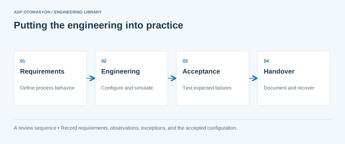
- Define the process states, timing requirements, and permitted behavior after a controller or communication failure.
- List controller, I/O, network, software, and license dependencies before choosing an architecture.
- Record acceptance results and prove that the delivered configuration can be restored from the handover package.
Follow an ASP project guide to connect the fundamentals with implementation and acceptance.
Primary references and further reading
Use the original specifications and product documentation for implementation details. The examples in this guide are illustrative engineering scenarios, not published project results.