
An industrial robot is rarely a standalone machine: it works inside a robot cell with guarding, tooling, sensors, conveyors, and a PLC that orchestrates the surrounding equipment. The robot controller and the PLC must exchange commands and status reliably, the safety system must protect people from a machine that moves with high speed and force, and the cell must integrate with the plant's network and MES. Cell integration is where robotics projects succeed or fail.
Cell Architecture
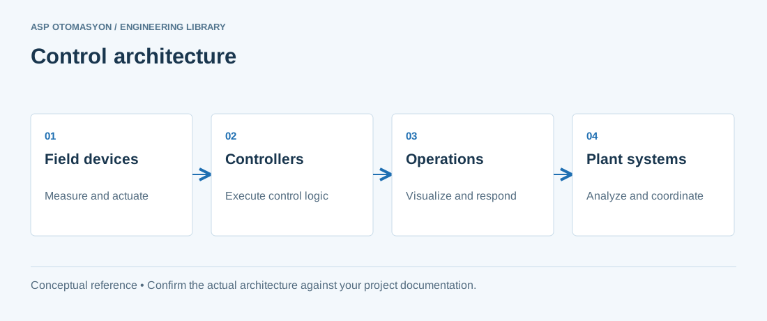
A typical cell has three control domains:
- Robot controller — executes the robot programs (motions, gripper actions) and owns the robot-specific safety functions.
- Cell PLC — controls conveyors, clamps, doors, vision triggers, and peripheral sensors; manages the cell sequence and reports to the plant SCADA/MES.
- Safety system — safety PLC or safety relays implementing guards, light curtains, emergency stops, and safe robot functions (safe stop, safe speed).
The interface between robot and PLC is typically a fieldbus connection (PROFINET, EtherNet/IP, EtherCAT) with a defined data block: PLC-to-robot commands (start cycle, select program, gripper open/close, reset) and robot-to-PLC status (running, done, fault, in position, mode). The signal list must be specified in a robot interface document before programming starts — vague interfaces are the most common source of integration rework.
Designing the Interface
- Define the handshake: every command that can fail needs a corresponding status and a timeout in the PLC. A missing handshake causes the classic deadlock — robot waiting for PLC, PLC waiting for robot.
- Use one-hot or strobed command words with explicit acknowledgment rather than level signals; a stuck bit then becomes visible in diagnostics.
- Make the interface mode-aware: automatic, manual/slow, maintenance, and emergency modes must be reflected to both sides.
- Include a heartbeat/watchdog in both directions so a dead partner is detected within the safety reaction budget.
- Document every signal with direction, type, meaning, and failure behavior in the interface document; version it with the programs.
Safety Design for Robot Cells
Robot safety is governed by ISO 10218-1/-2 (robot and robot system) with technical specification ISO/TS 15066 for collaborative operation. The risk assessment defines the required measures; typical cell measures include:
- Fixed guards and interlocked gates — the cell fence with monitored access points; gate opening stops the robot in a safe way.
- Light curtains and area scanners — protection of openings where material enters; muting may be needed for product passage, implemented with certified logic.
- Safe robot functions — Safe Torque Off (STO), Safe Stop 1/2, Safe Limited Speed — activated via the safety bus or hardwired safety inputs of the robot controller.
- Emergency stop chain — all E-stops (pendant, cell doors, plant line) wired into the safety circuit that cuts robot and peripheral energy.
- Restart procedures — after a stop, a deliberate reset and restart sequence prevents unexpected motion; the robot must not resume automatically.
For collaborative cells (robot sharing space with people), the risk assessment is stricter: force/power and speed limits per ISO/TS 15066, verification of contact forces, and clear rules for the handover zones between robot and operator. Treat the safety PLC program and the robot safety configuration as one system and validate them together.
Peripheral Integration
Vision systems (2D/3D) for part location or inspection are commonly integrated through the robot controller's vision interface or via the PLC: the PLC triggers the camera, receives the result (position offset, pass/fail), and passes it to the robot program. Grippers and end-of-arm tooling (EOAT) need their own I/O and diagnostics: clamping verification, air pressure monitoring, and tool change detection. Conveyor tracking (robot following a moving part) requires encoder synchronization — a feature to verify in the robot controller selection rather than assume.
Commissioning and Testing
Robot cell commissioning follows the FAT/SAT pattern with robot-specific additions:
- Path and reach validation — dry-run all programs at reduced speed, checking reachability and collision-free paths.
- Interface test — exercise every signal in the interface document in both directions, including fault injection.
- Safety validation — test every safety function individually and in combination (gate opened mid-motion, E-stop during high speed, restart behavior), documenting reaction times.
- Cycle time verification — measure the real cycle including handshakes, not just robot motion time.
- Recovery testing — simulate faults (gripper failure, vision timeout, communication loss) and verify the defined recovery sequences work.
Summary
Robot cell integration is an interface engineering problem: robot–PLC handshakes, safety system design, peripheral triggers, and plant integration. Specify the interface document first, design safety per ISO 10218 with the risk assessment as the driver, validate every function including failures, and measure real cycle times before accepting the cell. Robots are powerful; cells are what make them productive and safe.
Apply this to your project
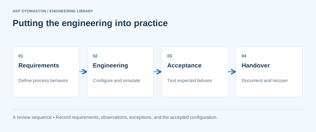
- Define the process states, timing requirements, and permitted behavior after a controller or communication failure.
- List controller, I/O, network, software, and license dependencies before choosing an architecture.
- Record acceptance results and prove that the delivered configuration can be restored from the handover package.
Follow an ASP project guide to connect the fundamentals with implementation and acceptance.
Primary references and further reading
Use the original specifications and product documentation for implementation details. The examples in this guide are illustrative engineering scenarios, not published project results.