
Motion control is the discipline of precisely controlling position, velocity, and torque in machines. At its core sits the servo system: a motor, a drive (amplifier), and a feedback device that continuously reports the actual motion back to the controller. From packaging machines and pick-and-place robots to CNC axes and winders, servo systems deliver the speed and accuracy that mechanical methods cannot. Understanding the components, selection criteria, and tuning process is essential for any automation engineer building or commissioning modern machines.
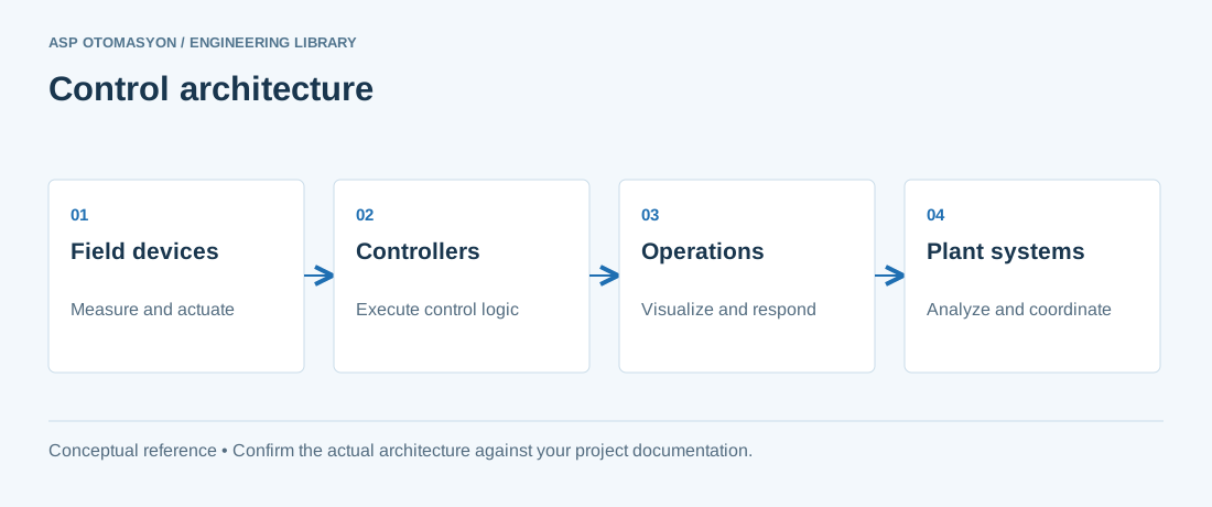
Servo System Building Blocks
A complete servo axis consists of four elements:
- Servo motor — a brushless AC motor (typically permanent-magnet synchronous, PMSM) with high peak torque relative to its size, low rotor inertia, and an integrated feedback device.
- Servo drive — a power converter that receives a motion command (position, velocity, or torque setpoint) and drives the motor windings using field-oriented control (FOC) at switching frequencies of 4–16 kHz.
- Feedback device — an incremental or absolute encoder (or resolver) mounted on the motor shaft, often supplemented by a second encoder or linear scale on the load for high-accuracy applications.
- Motion controller — a PLC-based or dedicated motion controller that generates the motion profiles (trapezoidal, S-curve, electronic cam) and closes the outer position loop.
Modern drives integrate the position loop and sometimes the velocity loop, so the controller only issues target positions at a fixed cycle time (1–8 ms typical, down to 125 µs for high-performance motion buses).
Selection Criteria
| Application demand | Design consideration |
|---|---|
| Peak torque at start/acceleration | Torque requirement at the worst-case duty point, including friction and gravity loads; size for peak, not RMS, with the drive's overload capability (typically 150–300% for 1–3 s) in mind. |
| Cycle time / acceleration | Motor inertia-to-load inertia ratio should generally stay below 10:1 (ideal 3–5:1) to keep the system controllable and stable. |
| Positioning accuracy | Encoder resolution: 17-bit single-turn and 23-bit multi-turn absolute encoders are common; add a linear scale where thermal growth or mechanical play dominates. |
| Speed range and constant-torque region | Continuous torque at rated speed; verify the drive's voltage and current limits for the required speed range. |
| Environment | IP rating, ambient temperature, and braking resistor sizing for regenerative (deceleration) energy. |
A common sizing mistake is ignoring the duty cycle. A motor that accelerates hard for 2 seconds and dwells for 10 seconds may need a small continuous rating but a large peak rating — selecting for continuous torque alone under-sizes the drive's peak current capability.
Feedback and Bus Architecture
Digital servo buses — EtherCAT, PROFINET (with IRT), EtherNet/IP with CIP Motion, and vendor-specific systems — carry the setpoints, actual values, and diagnostics between controller and drive. They also enable electronic gearing and electronic camming, where an axis follows a master axis or a cam table stored in the controller. Safety over the bus (STO, SS1, SS2 via PROFIsafe or FSoE) reduces wiring compared to hardwired safety relays, but always confirm the required Performance Level with the machinery risk assessment.
Commissioning and Tuning
Servo tuning is the iterative process of matching the drive's control gains to the mechanical system:
- Verify wiring and direction — confirm feedback polarity and motor phasing before enabling the axis.
- Measure the mechanics — run the automatic measurement routines: inertia identification, friction estimation, and resonance detection.
- Tune the velocity loop — raise the proportional gain until a slight oscillation appears, then back off 20–30%; add integral action to remove steady-state error.
- Tune the position loop — increase position-loop gain until the settling behavior meets the specification without audible noise or mechanical wear.
- Add feedforward — velocity and acceleration feedforward dramatically reduce following error in contouring and high-speed indexing applications.
- Apply notch filters — for resonances above the achievable bandwidth, notch filters suppress vibration without sacrificing loop gain.
- Verify under real duty — test the full cycle including worst-case payload, temperature, and supply-voltage variation.
Document the final gain set, the measured following error, and the resonance frequencies. On machines that will be copied, store the parameters in the drive and in the machine documentation so a replacement drive can be configured without re-tuning from scratch.
Common Faults and Diagnostics
Most servo faults are mechanical in origin: coupling backlash, bearing wear, or work-holding looseness appear as torque spikes or position-error alarms. Drive diagnostics (following error, overcurrent, overvoltage, overtemperature, encoder communication loss) point to the subsystem; a structured check of mechanics first, then cabling, then electronics saves hours. Keep spare feedback cables and connectors in stock — they are the most common intermittent failure point on high-flex applications.
Summary
Servo systems are the workhorse of precision automation. Size them on peak torque and duty cycle, select feedback resolution for the required accuracy, integrate them over a digital motion bus, and tune them methodically with automatic identification tools followed by verified real-cycle tests. A well-commissioned servo axis runs quietly, settles fast, and needs little maintenance beyond periodic inspection.
Apply this to your project
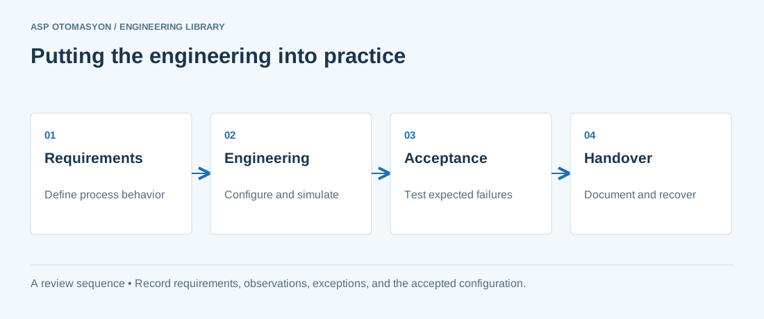
- Define the process states, timing requirements, and permitted behavior after a controller or communication failure.
- List controller, I/O, network, software, and license dependencies before choosing an architecture.
- Record acceptance results and prove that the delivered configuration can be restored from the handover package.
Follow an ASP project guide to connect the fundamentals with implementation and acceptance.
Primary references and further reading
Use the original specifications and product documentation for implementation details. The examples in this guide are illustrative engineering scenarios, not published project results.