
A brownfield cutover plan is a sequence of controlled changes with explicit decisions about whether to continue or return to the previous system. It must account for production state, people, wiring, software, communications, and recovery time. A backup file is only one part of that plan.
Design the requirement before the configuration
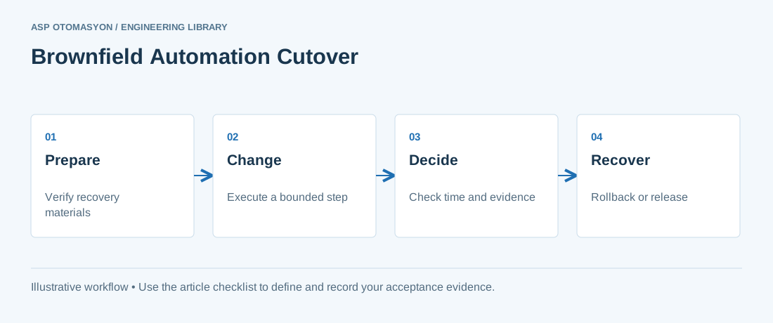
Divide the work into checkpoints that can be independently verified. Record prerequisites, responsible people, expected duration, evidence, and the latest time at which rollback can still finish inside the outage window. Some changes are not quickly reversible, such as removed wiring or altered field configuration. Identify those boundaries in advance. Define who owns the go/no-go decision and which observed conditions force a pause; avoid improvising acceptance criteria while the plant is waiting.
Worked scenario
Illustrative schedule: a six-hour outage reserves two hours for rollback and one hour for return-to-service checks. That leaves three hours for the initial change and its decision gate, not six. If a required interface remains unverified at that gate, the decision must use the agreed rollback rule. The durations are placeholders; estimate and rehearse the real activities for the site.
What to verify
| Check | Evidence to record |
|---|---|
| Before outage | Backups verified, materials checked, roles and communications agreed |
| Before disconnection | Process state and isolation confirmed by authorized personnel |
| Before commitment | Critical I/O and interfaces verified against the gate criteria |
| Before handover | Operators accept behavior and the final configuration is archived |
Acceptance and handover
Rehearse the sequence on a representative setup where practical. Include tool availability, licenses, spare equipment, remote support availability, and time needed to restore the previous configuration. Capture actual timings during execution and preserve the final record for the next upgrade.
Continue the engineering work
Use the related technical library for deeper background, or follow an ASP project guide to plan the implementation sequence.
Primary references and further reading
Use the original specifications and product documentation for implementation details. The examples in this guide are illustrative engineering scenarios, not published project results.