
PLC spare capacity is more than unused I/O terminals. A controller can have physical expansion room while memory, network connections, execution time, or power capacity limits the next project. Assess each resource against the installed application and a defined expansion scenario.
Design the requirement before the configuration
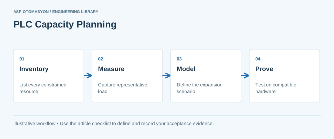
Inventory local and remote I/O, module compatibility, rack space, power budget, memory use, communication sessions, task loading, and supported software versions. Distinguish measured spare capacity from a procurement rule of thumb. A percentage reserved for I/O does not imply the same headroom in execution time or network bandwidth. Ask which future changes are realistic: more loops, faster tasks, an additional SCADA client, or a new protocol interface stress different resources.
Worked scenario
An illustrative system has 25% unused digital channels but needs a new high-speed analog acquisition function. Digital channel headroom does not solve the analog module, backplane, timing, or program requirements. Build a representative test and observe task execution and communication behavior under the proposed load before selecting the upgrade path.
What to verify
| Check | Evidence to record |
|---|---|
| Physical | Slots, enclosure space, power, heat, and spare modules |
| Execution | Task periods, observed execution, jitter, and watchdog margins |
| Data | Program and data memory, retention, and logging requirements |
| Connectivity | Driver load, sessions, nodes, and update-rate requirements |
Acceptance and handover
Record the baseline and expansion assumptions in the design review. Use manufacturer limits and observed behavior for the actual hardware and firmware combination. Include engineering-tool compatibility and backup/recovery needs; an unsupported programming environment can become a practical capacity constraint.
Continue the engineering work
Use the related technical library for deeper background, or follow an ASP project guide to plan the implementation sequence.
Primary references and further reading
Use the original specifications and product documentation for implementation details. The examples in this guide are illustrative engineering scenarios, not published project results.