
Every automation engineer's working life revolves around two drawing types: electrical schematics, which show how the control system is wired, and P&IDs (Piping and Instrumentation Diagrams), which show how the process is instrumented. Reading them fluently is the difference between working from evidence and working from guesswork — a technician who can read the drawing set troubleshoots in minutes what others probe for hours.
Electrical Schematics: Conventions
Industrial electrical drawings (IEC 61082 / ANSI style) follow conventions that make them readable:
- Reference designations — each component carries a class letter and number:
K1contactor,Q1circuit breaker,F1fuse,S1pushbutton,M1motor,X1terminal block. The same designation appears consistently across drawings. - Cross-references — a contact shown in a different drawing lists the location (e.g.,
K1coil on sheet 3, contacts on sheets 5–7); locating a coil and its contacts is the most common reading task. - Sheet structure — power circuits and control circuits are often on separate sheets; the control circuit is usually drawn with the load line at the bottom (IEC) or along the side (ANSI).
- Wire numbers — each wire has a unique number; the same number appears at both ends and at every junction, enabling continuity tracing from the drawing alone.
- Component states — contacts are drawn in their de-energized or normal state (what the component does with no power/no process), with a note for spring-return or process-actuated devices.
Reading order: start with the power distribution (incoming supply, main disconnect, breakers), then the power circuits (motors, heaters), then the control circuits (relays, PLC I/O), then the field wiring (terminal to device).
From Schematic to Panel and Field
The schematic describes the panel; the terminal diagram maps it to the real world:
- Terminal diagrams — show each terminal strip (
X1,X2…) with wire numbers and destinations (cable to field, cable to another panel). The terminal number plus cable number is the address of every field point. - Cable schedules — list every cable: number, type, cores, from/to, and spare cores. The spare-core policy (how many spares on an instrument cable) is an engineering decision visible here.
- I/O lists — the bridge between electrical and automation: every PLC/DCS channel with its tag, signal type, terminal, and cable. The I/O list is the contract the schematic and the PLC program both serve.
P&IDs: The Process Map
A P&ID (per ISA-5.1 / ISO 10628) shows the process equipment and every instrument, valve, and control function connected to it — without wire-level detail. Reading essentials:
- Instrument bubbles — circles with a tag: the first letters are the function (PT pressure transmitter, TT temperature transmitter, FT flow transmitter, LV level valve, PIC pressure indicating controller), the suffix is the loop number. A letter per position describes the full function (e.g.,
PIC= pressure indicating control). - Line symbols — the symbol inside the bubble shows where the instrument is: field-mounted (plain), panel-mounted (line across), or software/DCS function (dashed). A transmitter (no line through) vs a controller (line) changes where the logic lives.
- Control loops — a line connecting transmitter bubble, controller bubble, and final element (valve) shows the loop topology: simple feedback, cascade (two bubbles with an interconnecting line), or ratio (dashed lines for computed signals).
- Valve symbols — the actuator symbol (handwheel, diaphragm, motor) and the failure mode arrow (
FCfail closed,FOfail open,FLfail last) tell you the safety behavior when air/power is lost — critical information that never appears on electrical drawings. - Instrumentation letters —
Iindicator,Rrecorder,Aalarm,Sswitch,Yrelay/convertor: the bubblePIT(pressure indicating transmitter) describes both display and transmission.
Checking the Drawing Set
Drawings lie — they age, get revised incompletely, and inherit as-built drift. A field check method: pick one loop, verify it end to end — P&ID (instruments and function), loop diagram (wiring and power), I/O list (channel and terminal), schematic (actual terminals), and PLC tag (address and scaling) — and record every mismatch. Plants that do this regularly find their drawings become trustworthy again, which pays off in every later project.
Summary
Electrical schematics answer "how is it wired," P&IDs answer "how is it instrumented." Read schematics by reference designation, cross-reference, and wire number; read P&IDs by instrument bubble, function letters, and failure-mode symbols; and always reconcile both against the I/O list and loop diagrams. The drawing set is the plant's shared memory — the engineer who reads it fluently operates with evidence, not assumptions.
Apply this to your project
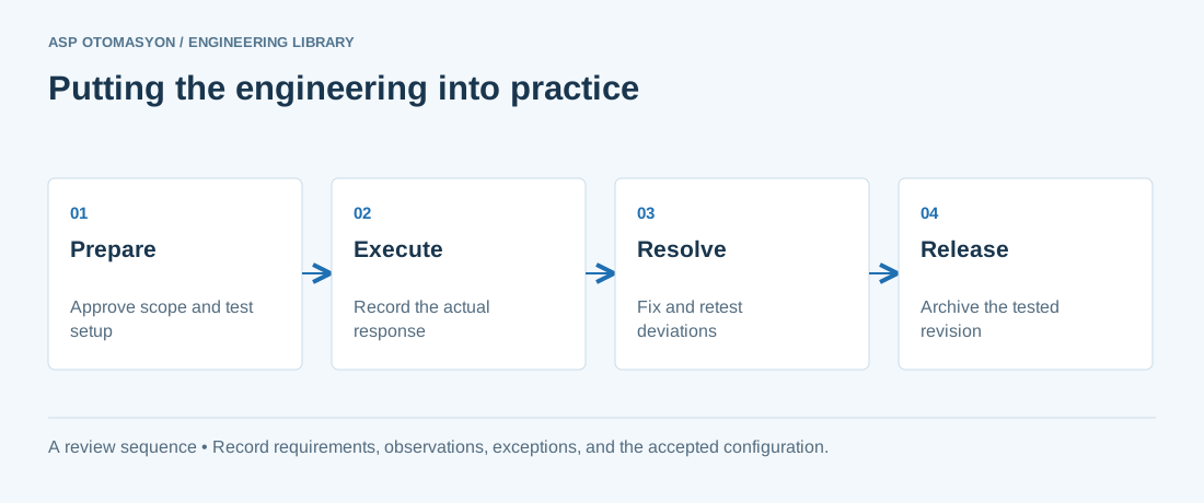
- Agree the test boundary and site authorization, especially where outputs or communications can affect operating equipment.
- Record expected and actual values, equipment identifiers, software revision, test conditions, and exceptions.
- Retest changed behavior and archive the final configuration with the test record and recovery instructions.
Follow an ASP project guide to connect the fundamentals with implementation and acceptance.
Primary references and further reading
Use the original specifications and product documentation for implementation details. The examples in this guide are illustrative engineering scenarios, not published project results.