
Radar is the dominant level measurement technology in modern process plants: non-contact, unaffected by density changes, and accurate across most services. But \"radar\" covers two distinct instrument families — guided wave radar (GWR), which sends the pulse down a probe in contact with the medium, and free-space (non-contact) radar, which transmits through the vapor space — and their application ranges barely overlap. Choosing between them is one of the most common instrument selection decisions, and the right answer is defined by the service: vapor, foam, turbulence, buildup, and geometry.
Both measure level as distance (time-of-flight) and compute level from the tank geometry; both offer interface measurement capability in the right configuration.
\n\n| Service condition | Better choice | Why |
|---|---|---|
| Low dielectric media (hydrocarbons, LPG, solvents, some organics) | Guided wave | The probe concentrates the signal; free-space radar struggles below ~1.5–2.0 dielectric constant. |
| Heavy vapor, steam, condensation, dust | Guided wave (or free-space with stilling well) | Vapor attenuation and condensation on the antenna degrade free-space; the GWR probe is unaffected. |
| Foam on the surface | Guided wave (usually) | Free-space reflects off the foam top (a false level); GWR sees through most light foams. Heavy/dense foam defeats both — test the service. |
| Agitators, turbulence, vortexing | Guided wave (in a stilling well) or free-space with the right placement | GWR probes damp turbulence; free-space needs a calm spot or stilling well. |
| Sticky, coating, or buildup services (asphalt, slurry) | Free-space (non-contact) | Buildup on a GWR probe attenuates the signal; a free-space antenna with air purge handles coating better. |
| Very large tanks, tall silos | Free-space | GWR cables are limited in length (tens of meters) and can sway in silos; free-space works to 100 m+. |
| Interface measurement (oil/water) | Guided wave | The probe sees the interface reflection; free-space cannot measure an interface. |
| Sanitary, hygienic, or high-temperature services | Both exist in special versions | Choose by the process conditions and the wetted materials; GWR with hygienic probe, free-space with flush antenna. |
Radar instruments are low-maintenance but not no-maintenance: the echo curve shows buildup, condensation, and false echoes long before the reading drifts; the instrument's diagnostics (signal quality, echo confidence) are monitored via HART or fieldbus (see the HART article) and trended like any process value. The service history rules: free-space antennas get inspected for coating and mechanical damage; GWR probes get checked for buildup, corrosion, and (in silos) cable tension. A radar that reports a stable level while the echo quality decays is telling you something — the diagnostics are the point.
\n\nGuided wave radar wins where the vapor is heavy, the dielectric is low, foam appears, or an interface must be measured; free-space radar wins where the product coats, the tank is very tall, or non-contact is mandatory. Decide by the service table, install with the correct probe/antenna practice, verify with a dip, and watch the echo curve as the diagnostic window. The level is the question; the service is the answer.
Follow an ASP project guide to connect the fundamentals with implementation and acceptance.

Use the original specifications and product documentation for implementation details. The examples in this guide are illustrative engineering scenarios, not published project results.
","markdown":"# Guided Wave vs Free-Space Radar Level Measurement\n\n> Radar is the dominant level measurement technology in modern process plants: non-contact, unaffected by density changes, and accurate across most services.\n\n- Canonical URL: https://wiki.aspotomasyon.com/article/radar-level-transmitters\n- Publisher: ASP OTOMASYON A.Ş. (ASP OTOMASYON Wiki)\n- Category: Field Devices & Instrumentation\n- Published: 2026-08-11 · Updated: 2026-09-13\n- Reading time: 4 min · Language: English\n\nRadar is the dominant level measurement technology in modern process plants: non-contact, unaffected by density changes, and accurate across most services. But \"radar\" covers two distinct instrument families — **guided wave radar (GWR)**, which sends the pulse down a probe in contact with the medium, and **free-space (non-contact) radar**, which transmits through the vapor space — and their application ranges barely overlap. Choosing between them is one of the most common instrument selection decisions, and the right answer is defined by the service: vapor, foam, turbulence, buildup, and geometry.\n\n\n\n*A measurement chain from the process to an application. Calibration, loop checks, and process validation answer different questions; retain evidence for each applicable check.*\n\n## How Each Works\n\n- **Free-space radar** — a microwave pulse (or FMCW sweep) travels through the vessel's vapor space, reflects off the product surface, and the flight time gives the distance. No contact with the process; the antenna sees the surface through the vapor.\n- **Guided wave radar** — the pulse travels along a probe (rod, cable, or coax) immersed in the medium; the reflection at the medium surface (and at interfaces) gives the level. The probe guides the signal, so the measurement is not affected by the vapor space or vessel internals.\n\nBoth measure level as distance (time-of-flight) and compute level from the tank geometry; both offer interface measurement capability in the right configuration.\n\n## Selection Decision Table\n\n| Service condition | Better choice | Why |\n| --- | --- | --- |\n| Low dielectric media (hydrocarbons, LPG, solvents, some organics) | Guided wave | The probe concentrates the signal; free-space radar struggles below ~1.5–2.0 dielectric constant. |\n| Heavy vapor, steam, condensation, dust | Guided wave (or free-space with stilling well) | Vapor attenuation and condensation on the antenna degrade free-space; the GWR probe is unaffected. |\n| Foam on the surface | Guided wave (usually) | Free-space reflects off the foam top (a false level); GWR sees through most light foams. Heavy/dense foam defeats both — test the service. |\n| Agitators, turbulence, vortexing | Guided wave (in a stilling well) or free-space with the right placement | GWR probes damp turbulence; free-space needs a calm spot or stilling well. |\n| Sticky, coating, or buildup services (asphalt, slurry) | Free-space (non-contact) | Buildup on a GWR probe attenuates the signal; a free-space antenna with air purge handles coating better. |\n| Very large tanks, tall silos | Free-space | GWR cables are limited in length (tens of meters) and can sway in silos; free-space works to 100 m+. |\n| Interface measurement (oil/water) | Guided wave | The probe sees the interface reflection; free-space cannot measure an interface. |\n| Sanitary, hygienic, or high-temperature services | Both exist in special versions | Choose by the process conditions and the wetted materials; GWR with hygienic probe, free-space with flush antenna. |\n\n## Installation Practice\n\n- **GWR** — the probe needs clearance from walls and nozzles (probe-to-wall spacing per the manual), the right probe type for the vessel (rigid rod for small tanks, cable for tall), and a stilling well or bypass for turbulent services. The probe end must not touch the vessel bottom; the dead zone at the top (where the pulse is still settling) sets the measurement's top limit.\n- **Free-space** — the antenna must see the surface: nozzle height limits the beam (the beam angle at the nozzle diameter), the mounting location avoids the fill stream and the vessel walls, and the reference height (the \"empty\" distance) is set by the antenna face. Condensation and buildup are managed with air purge, heating, or a stilling well.\n- **Verification** — both are verified against a manual tape/dip at commissioning (the echo map), and the echo curve is stored as the installation's baseline; a level transmitter's echo curve is its diagnostic window (see the smart transmitter article for the calibration discipline).\n\n## Diagnostics and Maintenance\n\nRadar instruments are low-maintenance but not no-maintenance: the echo curve shows buildup, condensation, and false echoes long before the reading drifts; the instrument's diagnostics (signal quality, echo confidence) are monitored via HART or fieldbus (see the HART article) and trended like any process value. The service history rules: free-space antennas get inspected for coating and mechanical damage; GWR probes get checked for buildup, corrosion, and (in silos) cable tension. A radar that reports a stable level while the echo quality decays is telling you something — the diagnostics are the point.\n\n## Summary\n\nGuided wave radar wins where the vapor is heavy, the dielectric is low, foam appears, or an interface must be measured; free-space radar wins where the product coats, the tank is very tall, or non-contact is mandatory. Decide by the service table, install with the correct probe/antenna practice, verify with a dip, and watch the echo curve as the diagnostic window. The level is the question; the service is the answer.\n\n## Apply this to your project\n\n- Confirm the instrument tag, range, engineering unit, process connection, and environmental suitability against approved documents.\n- Check the complete measurement chain, including sensor configuration, channel scaling, quality indication, and display units.\n- Record reference equipment, uncertainty where relevant, test points, deviations, and the final configuration.\n\n[Follow an ASP project guide](https://wiki.aspotomasyon.com/guides) to connect the fundamentals with implementation and acceptance.\n\n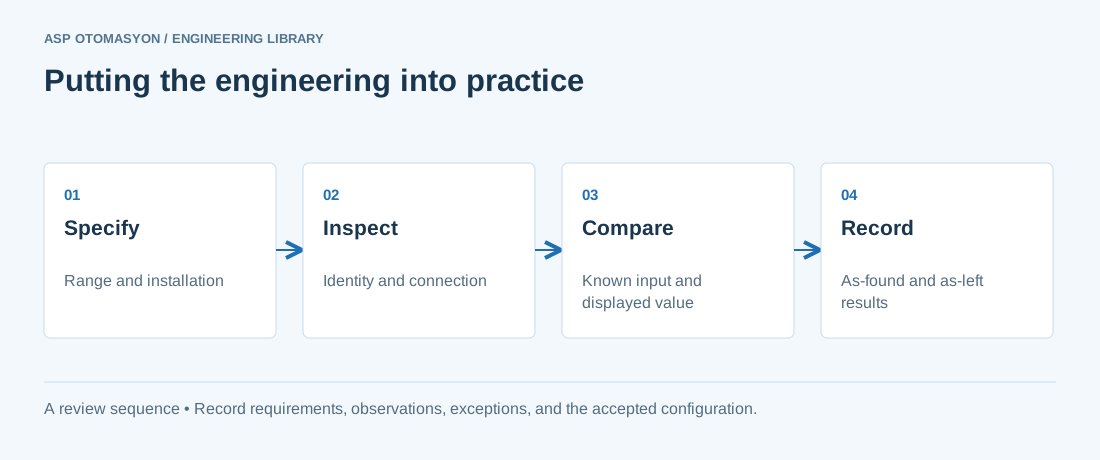\n\n*Engineering review sequence: Specify → Inspect → Compare → Record. Keep the recorded evidence with the accepted configuration.*\n\n## Primary references and further reading\n\nUse the original specifications and product documentation for implementation details. The examples in this guide are illustrative engineering scenarios, not published project results.\n\n- [FieldComm Group — HART technology](https://www.fieldcommgroup.org/technologies/hart)\n- [NIST — Policy on metrological traceability](https://www.nist.gov/calibrations/traceability)\n\n---\n\nCite the canonical article: https://wiki.aspotomasyon.com/article/radar-level-transmitters (Guided Wave vs Free-Space Radar Level Measurement, ASP OTOMASYON, updated 2026-09-13).\n","headings":[{"id":"how-each-works","title":"How Each Works"},{"id":"selection-decision-table","title":"Selection Decision Table"},{"id":"installation-practice","title":"Installation Practice"},{"id":"diagnostics-and-maintenance","title":"Diagnostics and Maintenance"},{"id":"summary","title":"Summary"},{"id":"apply-this-to-your-project","title":"Apply this to your project"},{"id":"primary-references-and-further-reading","title":"Primary references and further reading"}],"faq":[],"references":[{"name":"FieldComm Group — HART technology","url":"https://www.fieldcommgroup.org/technologies/hart"},{"name":"NIST — Policy on metrological traceability","url":"https://www.nist.gov/calibrations/traceability"}],"related":[{"slug":"level-measurement-technologies-selection","title":"Level Measurement Technologies: Selection Guide","summary":"Level measurement is one of the most common — and most varied — measurement tasks in industrial automation.","category":{"slug":"field-devices-instrumentation","name":"Field Devices & Instrumentation"},"url":"https://wiki.aspotomasyon.com/article/level-measurement-technologies-selection","markdown_url":"https://wiki.aspotomasyon.com/article/level-measurement-technologies-selection.md","api_url":"https://wiki.aspotomasyon.com/api/v1/articles/level-measurement-technologies-selection","published":"2026-08-06T12:26:37+00:00","modified":"2026-09-13T11:07:23+00:00","reading_minutes":5,"word_count":941,"image":"https://wiki.aspotomasyon.com/assets/social/level-measurement-technologies-selection-36094f42b2d7.png"},{"slug":"tank-farm-terminal-automation","title":"Tank Farm and Terminal Automation","summary":"Tank farms and product terminals — refineries' storage, oil depots, chemical bulk storage, and loading terminals — are where inventory becomes a measured…","category":{"slug":"process-industries-solutions","name":"Process Industries Solutions"},"url":"https://wiki.aspotomasyon.com/article/tank-farm-terminal-automation","markdown_url":"https://wiki.aspotomasyon.com/article/tank-farm-terminal-automation.md","api_url":"https://wiki.aspotomasyon.com/api/v1/articles/tank-farm-terminal-automation","published":"2026-08-11T13:05:24+00:00","modified":"2026-09-13T16:44:25+00:00","reading_minutes":4,"word_count":801,"image":"https://wiki.aspotomasyon.com/assets/social/tank-farm-terminal-automation-5c4ca9553923.png"},{"slug":"augmented-reality-industrial-maintenance","title":"Augmented Reality for Industrial Maintenance and Training","summary":"Augmented reality (AR) overlays digital information on the physical world: a technician looking at a machine sees its nameplate data, maintenance history, or…","category":{"slug":"digital-transformation","name":"Digital Transformation"},"url":"https://wiki.aspotomasyon.com/article/augmented-reality-industrial-maintenance","markdown_url":"https://wiki.aspotomasyon.com/article/augmented-reality-industrial-maintenance.md","api_url":"https://wiki.aspotomasyon.com/api/v1/articles/augmented-reality-industrial-maintenance","published":"2026-08-11T13:05:19+00:00","modified":"2026-09-13T11:07:23+00:00","reading_minutes":4,"word_count":870,"image":"https://wiki.aspotomasyon.com/assets/social/augmented-reality-industrial-maintenance-a305b0c01449.png"},{"slug":"opc-da-to-ua-migration-guide","title":"Migrating from OPC DA to OPC UA","summary":"Migrating from OPC DA to OPC UA is one of the most common infrastructure projects in industrial IT. OPC DA (Data Access) has served industry for more than two…","category":{"slug":"opc-solutions","name":"OPC Solutions"},"url":"https://wiki.aspotomasyon.com/article/opc-da-to-ua-migration-guide","markdown_url":"https://wiki.aspotomasyon.com/article/opc-da-to-ua-migration-guide.md","api_url":"https://wiki.aspotomasyon.com/api/v1/articles/opc-da-to-ua-migration-guide","published":"2026-08-06T12:26:37+00:00","modified":"2026-09-13T11:07:23+00:00","reading_minutes":5,"word_count":999,"image":"https://wiki.aspotomasyon.com/assets/social/opc-da-to-ua-migration-guide-4dc7a9d57cd5.png"}],"citation":"ASP OTOMASYON. Guided Wave vs Free-Space Radar Level Measurement. Updated 2026-09-13. https://wiki.aspotomasyon.com/article/radar-level-transmitters"}}