
Writing reliable, maintainable PLC code is critical for industrial automation systems that must operate 24/7 in harsh environments. This guide covers established best practices for PLC programming using the IEC 61131-3 standard, with practical examples applicable to platforms from Siemens, Rockwell, Schneider Electric, and CODESYS-based controllers.
The IEC 61131-3 standard defines five programming languages for industrial controllers. Choosing the right language for each task is the first step toward clean, maintainable code:
\n\nWell-organized PLC code follows a modular architecture that separates concerns and enables independent testing:
\n\nConsistent naming makes code self-documenting and searchable. Follow these conventions:
\n\n| Element | Convention | Example |
|---|---|---|
| Variables | Prefix + Area + Equipment + Suffix | xP100_Motor01_Run |
| Prefix: BOOL | x (input), y (output), b (internal) | xSensor01, yValve01 |
| Prefix: Analog | i (input), q (output), r (real/internal) | iTT101_PV, rSetpoint |
| Programs | P_ + Area + Function | P_Area01_Motors |
| Function Blocks | FB_ + Equipment Type | FB_MotorControl |
| Constants | c_ + descriptive name | c_MAX_SPEED |
Robust PLC programs must handle faults gracefully. Implement these patterns:
\n\nThe following Structured Text example demonstrates a reusable motor control function block with fault handling:
\n\nFUNCTION_BLOCK FB_MotorControl\nVAR_INPUT\n xStart : BOOL; // Start command from HMI\n xStop : BOOL; // Stop command from HMI\n xFeedback : BOOL; // Running feedback from field\n xFaultReset : BOOL; // Fault reset command\n tStartDelay : TIME := T#5S; // Max time to wait for feedback\nEND_VAR\nVAR_OUTPUT\n yRun : BOOL; // Output to motor starter\n xRunning : BOOL; // Confirmed running status\n xFault : BOOL; // Fault flag\n sFaultMsg : STRING; // Fault description\nEND_VAR\nVAR\n xStartPrev : BOOL;\n tonStart : TON;\nEND_VAR\n\n// Detect start command rising edge\nxRisingEdge := xStart AND NOT xStartPrev;\nxStartPrev := xStart;\n\n// Start delay timer (watchdog)\ntonStart(IN := xStartPrev AND NOT xFeedback, PT := tStartDelay);\n\n// Motor output logic\nIF xFault THEN\n yRun := FALSE;\nELSIF xStop THEN\n yRun := FALSE;\nELSIF xStartPrev THEN\n yRun := TRUE;\nEND_IF;\n\n// Fault detection\nIF tonStart.Q THEN\n xFault := TRUE;\n sFaultMsg := \"Motor failed to start within timeout\";\nEND_IF;\n\n// Fault reset\nIF xFaultReset AND xFault THEN\n tonStart(IN := FALSE); // Reset the watchdog timer\n xFault := FALSE;\n sFaultMsg := \"\";\nEND_IF;\n\n// Status output\nxRunning := yRun AND xFeedback;Testing PLC code requires a different approach than software testing:
\n\n| Step | Task | Status |
|---|---|---|
| 1 | Verify all I/O point-to-point wiring | Pending |
| 2 | Confirm signal conditioning and scaling | Pending |
| 3 | Test all interlocks and safety functions | Pending |
| 4 | Validate alarm messages and priorities | Pending |
| 5 | Tune PID loops (start with conservative gains) | Pending |
| 6 | Remove all forced I/O signals | Pending |
| 7 | Backup final program and document version | Pending |
| 8 | Train operators on new functionality | Pending |
Clean PLC code is not just about making it work — it is about making it maintainable for the next engineer who will modify it at 3 AM during a production outage.
Keep the source project, controller firmware, library versions, and test evidence under a controlled release identifier. Define startup values, retained-state behavior, and recovery after interrupted communications. Test changes against both normal sequences and abnormal inputs in an approved environment. An online comparison is useful, but it does not replace a documented backup and a proven recovery procedure.
Continue with the related practical guide.
Follow an ASP project guide to connect the fundamentals with implementation and acceptance.

Use the original specifications and product documentation for implementation details. The examples in this guide are illustrative engineering scenarios, not published project results.
","markdown":"# PLC Programming Best Practices\n\n> Writing reliable, maintainable PLC code is critical for industrial automation systems that must operate 24/7 in harsh environments.\n\n- Canonical URL: https://wiki.aspotomasyon.com/article/plc-programming-best-practices\n- Publisher: ASP OTOMASYON A.Ş. (ASP OTOMASYON Wiki)\n- Category: Automation Systems\n- Published: 2026-05-12 · Updated: 2026-09-13\n- Reading time: 5 min · Language: English\n\nWriting reliable, maintainable PLC code is critical for industrial automation systems that must operate 24/7 in harsh environments. This guide covers established best practices for PLC programming using the **IEC 61131-3** standard, with practical examples applicable to platforms from Siemens, Rockwell, Schneider Electric, and CODESYS-based controllers.\n\n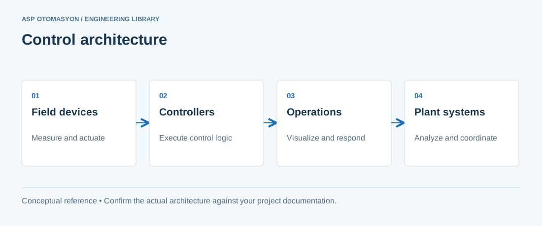\n\n*Conceptual control-system layers. Safety functions, communication paths, and redundancy must be designed for the application; the diagram is not a wiring or safety design.*\n\n## IEC 61131-3 Programming Languages\n\nThe IEC 61131-3 standard defines five programming languages for industrial controllers. Choosing the right language for each task is the first step toward clean, maintainable code:\n\n- **Ladder Logic (LD)** — Best for discrete logic, interlocks, and sequences that mirror relay circuits. Widely understood by electricians and maintenance staff.\n- **Function Block Diagram (FBD)** — Ideal for continuous process control, PID loops, and signal processing. Visual representation of data flow between blocks.\n- **Structured Text (ST)** — A Pascal-like text language best suited for complex algorithms, data manipulation, calculations, and state machines.\n- **Instruction List (IL)** — Assembly-like language, now deprecated in IEC 61131-3 Ed. 4. Avoid for new projects.\n- **Sequential Function Chart (SFC)** — Excellent for batch sequences, step-based processes, and recipe management. Provides clear visualization of process phases.\n\n## Code Organization\n\nWell-organized PLC code follows a modular architecture that separates concerns and enables independent testing:\n\n1. **Organize by Function** — Group related logic into Program Organization Units (POUs): one POU per motor, valve, or control loop.\n2. **Use a Main Task Dispatcher** — The main program should only call subroutines, never contain control logic directly.\n3. **Separate Safety from Standard** — Safety-related logic must reside in dedicated safety programs with clear boundaries.\n4. **Layer Your Architecture** — Field I/O to Signal Conditioning to Control Logic to Supervisory Setpoints to HMI Interface.\n\n## Naming Conventions\n\nConsistent naming makes code self-documenting and searchable. Follow these conventions:\n\n| Element | Convention | Example |\n| --- | --- | --- |\n| Variables | Prefix + Area + Equipment + Suffix | `xP100_Motor01_Run` |\n| Prefix: BOOL | x (input), y (output), b (internal) | `xSensor01`, `yValve01` |\n| Prefix: Analog | i (input), q (output), r (real/internal) | `iTT101_PV`, `rSetpoint` |\n| Programs | P_ + Area + Function | `P_Area01_Motors` |\n| Function Blocks | FB_ + Equipment Type | `FB_MotorControl` |\n| Constants | c_ + descriptive name | `c_MAX_SPEED` |\n\n## Error Handling Strategies\n\nRobust PLC programs must handle faults gracefully. Implement these patterns:\n\n- **Watchdog Timers** — Monitor communication timeouts with field devices. If no response within the configured window, set a fault flag and revert to a safe state.\n- **Range Checking** — Validate all analog inputs against instrument range limits. Per NAMUR NE43, values below 3.6 mA or above 21.0 mA on a 4–20 mA signal indicate wiring faults or sensor failures. Values in the 3.6–3.8 mA and 20.5–21.0 mA ranges indicate cautionary zones requiring attention.\n- **Interlock Prioritization** — Safety interlocks must override operator commands. Implement as normally-closed (fail-safe) where possible.\n- **State Machine Recovery** — Every state machine must include an explicit ERROR state with diagnostic information and a defined recovery path.\n\n## Structured Text Example: Motor Control\n\nThe following Structured Text example demonstrates a reusable motor control function block with fault handling:\n\n```\nFUNCTION_BLOCK FB_MotorControl\nVAR_INPUT\n xStart : BOOL; // Start command from HMI\n xStop : BOOL; // Stop command from HMI\n xFeedback : BOOL; // Running feedback from field\n xFaultReset : BOOL; // Fault reset command\n tStartDelay : TIME := T#5S; // Max time to wait for feedback\nEND_VAR\nVAR_OUTPUT\n yRun : BOOL; // Output to motor starter\n xRunning : BOOL; // Confirmed running status\n xFault : BOOL; // Fault flag\n sFaultMsg : STRING; // Fault description\nEND_VAR\nVAR\n xStartPrev : BOOL;\n tonStart : TON;\nEND_VAR\n\n// Detect start command rising edge\nxRisingEdge := xStart AND NOT xStartPrev;\nxStartPrev := xStart;\n\n// Start delay timer (watchdog)\ntonStart(IN := xStartPrev AND NOT xFeedback, PT := tStartDelay);\n\n// Motor output logic\nIF xFault THEN\n yRun := FALSE;\nELSIF xStop THEN\n yRun := FALSE;\nELSIF xStartPrev THEN\n yRun := TRUE;\nEND_IF;\n\n// Fault detection\nIF tonStart.Q THEN\n xFault := TRUE;\n sFaultMsg := \"Motor failed to start within timeout\";\nEND_IF;\n\n// Fault reset\nIF xFaultReset AND xFault THEN\n tonStart(IN := FALSE); // Reset the watchdog timer\n xFault := FALSE;\n sFaultMsg := \"\";\nEND_IF;\n\n// Status output\nxRunning := yRun AND xFeedback;\n```\n\n## Testing and Debugging\n\nTesting PLC code requires a different approach than software testing:\n\n1. **Simulate First** — Use the PLC vendor simulation environment to test logic before connecting to real hardware.\n2. **Force I/O Carefully** — Document all forced signals and remove them before commissioning. Use a force-register log.\n3. **Test Fault Paths** — Deliberately trigger each fault condition to verify alarm messages, safe-state behavior, and recovery procedures.\n4. **Use Trend Recording** — Record critical variables during testing to analyze timing, ramp rates, and loop performance.\n5. **Peer Review** — Have another engineer review control logic before deployment. ASP OTOMASYON enforces peer review on all safety-related code.\n\n## Commissioning Checklist\n\n| Step | Task | Status |\n| --- | --- | --- |\n| 1 | Verify all I/O point-to-point wiring | Pending |\n| 2 | Confirm signal conditioning and scaling | Pending |\n| 3 | Test all interlocks and safety functions | Pending |\n| 4 | Validate alarm messages and priorities | Pending |\n| 5 | Tune PID loops (start with conservative gains) | Pending |\n| 6 | Remove all forced I/O signals | Pending |\n| 7 | Backup final program and document version | Pending |\n| 8 | Train operators on new functionality | Pending |\n\n> Clean PLC code is not just about making it work — it is about making it maintainable for the next engineer who will modify it at 3 AM during a production outage.\n\n---\n\n## References & Further Reading\n\n1. [IEC 61131-3: Programmable Controllers — Programming Languages](https://www.iec.ch) — International standard defining Ladder Diagram, Structured Text, Function Block Diagram, Sequential Function Chart, and Instruction List for PLC programming.\n2. [Siemens TIA Portal Documentation](https://www.siemens.com/en-us/products/tia-portal/) — Official Siemens engineering framework for S7-1200/S7-1500 PLC programming with IEC 61131-3 language support.\n3. [Rockwell Automation Studio 5000 Logix Designer](https://www.rockwellautomation.com/en-us/products/software/factorytalk/designsuite/studio-5000.html) — Official Rockwell Software for ControlLogix/CompactLogix PLC programming, configuration, and diagnostics.\n4. [CODESYS Development System](https://en.wikipedia.org/wiki/CODESYS) — Official IEC 61131-3 integrated development environment used by ABB AC500, Schneider Electric, and WAGO controllers.\n5. [Schneider Electric EcoStruxure — PLC and SCADA Platform](https://en.wikipedia.org/wiki/Schneider_Electric) — Official documentation for Schneider Electric's PLC programming environment and industrial software ecosystem.\n\n## Make changes reviewable and recoverable\n\nKeep the source project, controller firmware, library versions, and test evidence under a controlled release identifier. Define startup values, retained-state behavior, and recovery after interrupted communications. Test changes against both normal sequences and abnormal inputs in an approved environment. An online comparison is useful, but it does not replace a documented backup and a proven recovery procedure.\n\nContinue with [the related practical guide](https://wiki.aspotomasyon.com/article/automation-handover-documentation).\n\n## Apply this to your project\n\n- Define the process states, timing requirements, and permitted behavior after a controller or communication failure.\n- List controller, I/O, network, software, and license dependencies before choosing an architecture.\n- Record acceptance results and prove that the delivered configuration can be restored from the handover package.\n\n[Follow an ASP project guide](https://wiki.aspotomasyon.com/guides) to connect the fundamentals with implementation and acceptance.\n\n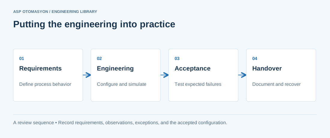\n\n*Engineering review sequence: Requirements → Engineering → Acceptance → Handover. Keep the recorded evidence with the accepted configuration.*\n\n## Primary references and further reading\n\nUse the original specifications and product documentation for implementation details. The examples in this guide are illustrative engineering scenarios, not published project results.\n\n- [ABB — System 800xA architecture and product documentation](https://new.abb.com/control-systems/system-800xa)\n- [NIST SP 800-82 Rev. 3 — OT architecture and security guidance](https://csrc.nist.gov/pubs/sp/800/82/r3/final)\n\n---\n\nCite the canonical article: https://wiki.aspotomasyon.com/article/plc-programming-best-practices (PLC Programming Best Practices, ASP OTOMASYON, updated 2026-09-13).\n","headings":[{"id":"iec-61131-3-programming-languages","title":"IEC 61131-3 Programming Languages"},{"id":"code-organization","title":"Code Organization"},{"id":"naming-conventions","title":"Naming Conventions"},{"id":"error-handling-strategies","title":"Error Handling Strategies"},{"id":"structured-text-example-motor-control","title":"Structured Text Example: Motor Control"},{"id":"testing-and-debugging","title":"Testing and Debugging"},{"id":"commissioning-checklist","title":"Commissioning Checklist"},{"id":"references-further-reading","title":"References & Further Reading"},{"id":"make-changes-reviewable-and-recoverable","title":"Make changes reviewable and recoverable"},{"id":"apply-this-to-your-project","title":"Apply this to your project"},{"id":"primary-references-and-further-reading","title":"Primary references and further reading"}],"faq":[],"references":[{"name":"IEC 61131-3: Programmable Controllers — Programming Languages","url":"https://www.iec.ch"},{"name":"Siemens TIA Portal Documentation","url":"https://www.siemens.com/en-us/products/tia-portal/"},{"name":"Rockwell Automation Studio 5000 Logix Designer","url":"https://www.rockwellautomation.com/en-us/products/software/factorytalk/designsuite/studio-5000.html"},{"name":"CODESYS Development System","url":"https://en.wikipedia.org/wiki/CODESYS"},{"name":"Schneider Electric EcoStruxure — PLC and SCADA Platform","url":"https://en.wikipedia.org/wiki/Schneider_Electric"},{"name":"ABB — System 800xA architecture and product documentation","url":"https://new.abb.com/control-systems/system-800xa"},{"name":"NIST SP 800-82 Rev. 3 — OT architecture and security guidance","url":"https://csrc.nist.gov/pubs/sp/800/82/r3/final"}],"related":[{"slug":"packml-machine-state-model-omac","title":"PackML Machine State Model: Modes, States, and Tags","summary":"PackML gives packaging machines one unit mode model, one standard state model, and standard tags, so a line controller can command and read every machine the…","category":{"slug":"automation-systems","name":"Automation Systems"},"url":"https://wiki.aspotomasyon.com/article/packml-machine-state-model-omac","markdown_url":"https://wiki.aspotomasyon.com/article/packml-machine-state-model-omac.md","api_url":"https://wiki.aspotomasyon.com/api/v1/articles/packml-machine-state-model-omac","published":"2026-10-11T11:46:21+00:00","modified":"2026-10-11T11:46:21+00:00","reading_minutes":9,"word_count":1906,"image":"https://wiki.aspotomasyon.com/assets/social/packml-machine-state-model-omac-762e3ee18199.png"},{"slug":"iec-61131-3-plc-programming-languages","title":"IEC 61131-3: PLC Programming Languages","summary":"The IEC 61131-3 standard is the international benchmark for programmable logic controller (PLC) and distributed control system (DCS) programming.","category":{"slug":"automation-systems","name":"Automation Systems"},"url":"https://wiki.aspotomasyon.com/article/iec-61131-3-plc-programming-languages","markdown_url":"https://wiki.aspotomasyon.com/article/iec-61131-3-plc-programming-languages.md","api_url":"https://wiki.aspotomasyon.com/api/v1/articles/iec-61131-3-plc-programming-languages","published":"2026-07-21T14:45:28+00:00","modified":"2026-09-13T11:07:23+00:00","reading_minutes":5,"word_count":1025,"image":"https://wiki.aspotomasyon.com/assets/social/iec-61131-3-plc-programming-languages-25b7213c7dc3.png"},{"slug":"secure-plc-application-programming","title":"Secure PLC Application Programming and Logic Protection","summary":"Most ICS security guidance stops at the network: firewalls, segmentation, and monitoring.","category":{"slug":"industrial-cybersecurity","name":"Industrial Cybersecurity"},"url":"https://wiki.aspotomasyon.com/article/secure-plc-application-programming","markdown_url":"https://wiki.aspotomasyon.com/article/secure-plc-application-programming.md","api_url":"https://wiki.aspotomasyon.com/api/v1/articles/secure-plc-application-programming","published":"2026-08-11T13:05:24+00:00","modified":"2026-09-13T11:07:23+00:00","reading_minutes":5,"word_count":885,"image":"https://wiki.aspotomasyon.com/assets/social/secure-plc-application-programming-cbbb68d7d194.png"},{"slug":"sequential-function-chart-programming","title":"Sequential Function Chart (SFC) Programming for Process Sequences","summary":"Sequential Function Chart (SFC) is the IEC 61131-3 programming language designed for state-based, sequential control.","category":{"slug":"automation-systems","name":"Automation Systems"},"url":"https://wiki.aspotomasyon.com/article/sequential-function-chart-programming","markdown_url":"https://wiki.aspotomasyon.com/article/sequential-function-chart-programming.md","api_url":"https://wiki.aspotomasyon.com/api/v1/articles/sequential-function-chart-programming","published":"2026-08-11T13:05:19+00:00","modified":"2026-09-13T11:07:23+00:00","reading_minutes":4,"word_count":858,"image":"https://wiki.aspotomasyon.com/assets/social/sequential-function-chart-programming-c62ac92e9f4c.png"}],"citation":"ASP OTOMASYON. PLC Programming Best Practices. Updated 2026-09-13. https://wiki.aspotomasyon.com/article/plc-programming-best-practices"}}