
The instrument tag is the identity of every measurement and control function in a plant: PT-1001, FV-2042, TE-3108 — and the tagging standard is the language the whole plant speaks. ANSI/ISA-5.1 (\"Instrumentation Symbols and Identification\") defines the letters, the numbering, and the symbols; consistent tagging is what makes drawings readable, databases joinable, and work orders unambiguous. This article covers the standard's structure and the practical rules that keep a plant's instrument identification coherent for decades.
An instrument tag per ISA-5.1 has three parts:
\n\nPT pressure transmitter, PIC pressure indicating controller, FT flow transmitter, FIC flow indicating controller, LSHH level switch high-high.FT-1001, FIC-1001, FV-1001.PT-1001-1 for the first sensing point).The letters are English-based by standard, but the logic transfers to any language — the tag is an ID, the function letters are its semantics.
\n\nISA-5.1 also defines the symbols: the instrument bubble (circle) with the tag inside, the line conventions (field-mounted, panel-mounted, software function — see the P&ID article), and the signal lines (pneumatic, electric, data link). The bubble's position tells the reader where the function lives: a transmitter bubble (no horizontal line) is field hardware; a line through it is a panel device; a dashed circle is a DCS/software function. The discipline: draw the P&ID exactly as built — the symbol set is the plant's shared vocabulary, and a sloppy P&ID is a sloppy plant (see the loop diagram article for the detail level below).
\n\nThe instrument database (CMMS or dedicated) is where tagging lives operationally:
\n\nInstrument tagging per ISA-5.1 is the plant's identification language: function letters for the meaning, loop numbers for the identity, and consistent usage across drawings, systems, and records. Decide the conventions once, enforce uniqueness and non-reuse, keep the tag functional rather than physical, and manage the tag database as the primary key of the instrument lifecycle. When the plant's systems disagree, the tag is the judge; make it a reliable one.
Follow an ASP project guide to connect the fundamentals with implementation and acceptance.

Use the original specifications and product documentation for implementation details. The examples in this guide are illustrative engineering scenarios, not published project results.
","markdown":"# Instrument Tagging and Identification Standards (ISA-5.1)\n\n> The instrument tag is the identity of every measurement and control function in a plant: PT-1001 , FV-2042 , TE-3108 — and the tagging standard is the language…\n\n- Canonical URL: https://wiki.aspotomasyon.com/article/instrument-tagging-standards\n- Publisher: ASP OTOMASYON A.Ş. (ASP OTOMASYON Wiki)\n- Category: Field Devices & Instrumentation\n- Published: 2026-08-11 · Updated: 2026-09-13\n- Reading time: 4 min · Language: English\n\nThe instrument tag is the identity of every measurement and control function in a plant: `PT-1001`, `FV-2042`, `TE-3108` — and the tagging standard is the language the whole plant speaks. **ANSI/ISA-5.1** (\"Instrumentation Symbols and Identification\") defines the letters, the numbering, and the symbols; consistent tagging is what makes drawings readable, databases joinable, and work orders unambiguous. This article covers the standard's structure and the practical rules that keep a plant's instrument identification coherent for decades.\n\n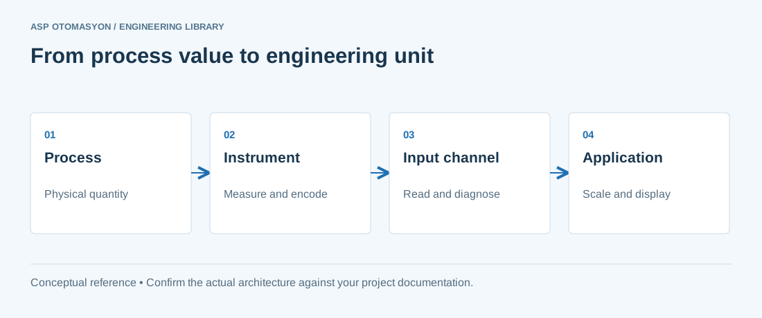\n\n*A measurement chain from the process to an application. Calibration, loop checks, and process validation answer different questions; retain evidence for each applicable check.*\n\n## The Tag Structure\n\nAn instrument tag per ISA-5.1 has three parts:\n\n- **Function letters** — the first letter is the measured variable (P pressure, T temperature, F flow, L level, A analysis, I current, W weight), the succeeding letters the functions (I indicator, C controller, T transmitter, R recorder, A alarm, S switch, V valve, Y relay/compute). Examples: `PT` pressure transmitter, `PIC` pressure indicating controller, `FT` flow transmitter, `FIC` flow indicating controller, `LSHH` level switch high-high.\n- **Loop number** — the identifier of the loop (1001, 2042…): the same loop number appears on the transmitter, the controller, and the valve (the loop is one functional entity), with the function letters distinguishing the elements: `FT-1001` , `FIC-1001` , `FV-1001` .\n- **Suffix letters** — optional modifiers for elements in the same loop (A, B: redundant or multi-element) and for device-specific numbering (e.g., `PT-1001-1` for the first sensing point).\n\nThe letters are English-based by standard, but the logic transfers to any language — the tag is an ID, the function letters are its semantics.\n\n## Tagging Conventions That Survive\n\n- **Unique everywhere** — one tag, one instrument: the tag appears identically on the P&ID, the loop diagram, the I/O list, the DCS database, the calibration records, and the nameplate. The rule sounds trivial; plants violate it daily (the P&ID says PT-1001, the DCS says AI-1037, the work order says \"pressure switch boiler\").\n- **Plant-wide vs unit-specific** — the loop number convention (per-unit ranges: unit 1 uses 1000s, unit 2 uses 2000s, or a plant-wide sequence) is decided once and enforced; the choice matters less than the consistency.\n- **Functional, not physical** — the tag follows the function, not the location: a transmitter moved from tank A to tank B keeps its tag if it serves the same loop — or gets a new loop number if the function changed; the change record follows the tag.\n- **No meaning overloading** — the tag is an identifier, not a description: adding service codes into the tag (PT-1001-STEAM) creates two naming systems; the service lives in the instrument database (see the data sheet article), the tag stays standard.\n- **Logical next in line** — new instruments take the next free loop number; retired numbers are never reused (the historical record stays unambiguous).\n\n## Symbols and the Drawing Set\n\nISA-5.1 also defines the symbols: the instrument bubble (circle) with the tag inside, the line conventions (field-mounted, panel-mounted, software function — see the P&ID article), and the signal lines (pneumatic, electric, data link). The bubble's position tells the reader where the function lives: a transmitter bubble (no horizontal line) is field hardware; a line through it is a panel device; a dashed circle is a DCS/software function. The discipline: draw the P&ID exactly as built — the symbol set is the plant's shared vocabulary, and a sloppy P&ID is a sloppy plant (see the loop diagram article for the detail level below).\n\n## Tag Management in the Digital Age\n\nThe instrument database (CMMS or dedicated) is where tagging lives operationally:\n\n- The tag is the primary key: every record (calibration, work order, spare part, configuration) hangs off the tag.\n- Tag creation and changes are controlled: the new-tag process (who may allocate, what the minimum metadata is) prevents the tag chaos that comes with projects and modifications.\n- The DCS/SCADA tags map to the field tags (the I/O list is the mapping); the mapping review after every project is a standard checklist item (see the commissioning article).\n- Retirements are recorded: a decommissioned tag keeps its history and is marked retired — never deleted, never reused.\n\n## Summary\n\nInstrument tagging per ISA-5.1 is the plant's identification language: function letters for the meaning, loop numbers for the identity, and consistent usage across drawings, systems, and records. Decide the conventions once, enforce uniqueness and non-reuse, keep the tag functional rather than physical, and manage the tag database as the primary key of the instrument lifecycle. When the plant's systems disagree, the tag is the judge; make it a reliable one.\n\n## Apply this to your project\n\n- Confirm the instrument tag, range, engineering unit, process connection, and environmental suitability against approved documents.\n- Check the complete measurement chain, including sensor configuration, channel scaling, quality indication, and display units.\n- Record reference equipment, uncertainty where relevant, test points, deviations, and the final configuration.\n\n[Follow an ASP project guide](https://wiki.aspotomasyon.com/guides) to connect the fundamentals with implementation and acceptance.\n\n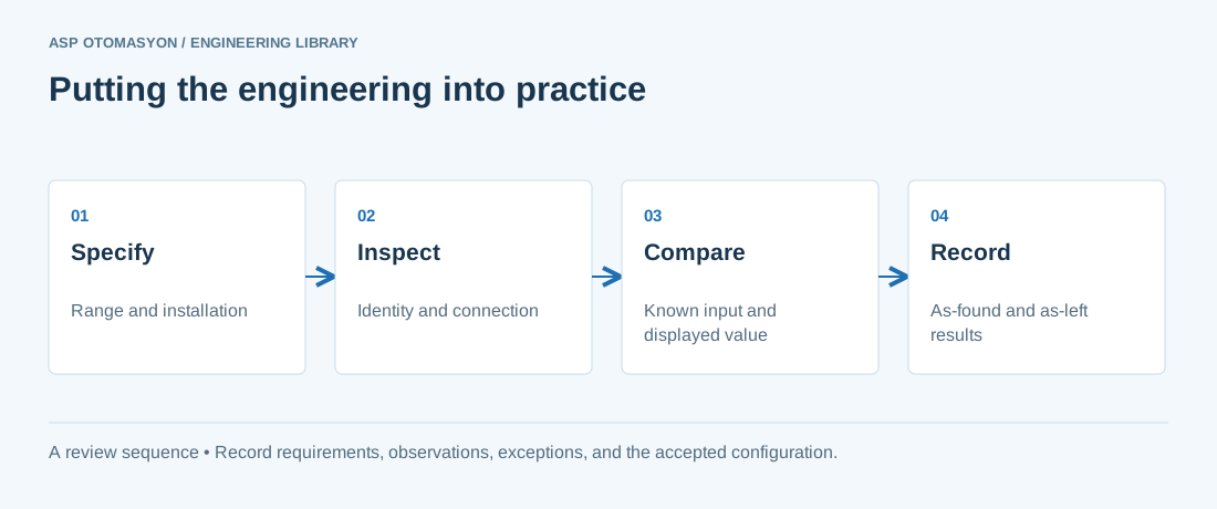\n\n*Engineering review sequence: Specify → Inspect → Compare → Record. Keep the recorded evidence with the accepted configuration.*\n\n## Primary references and further reading\n\nUse the original specifications and product documentation for implementation details. The examples in this guide are illustrative engineering scenarios, not published project results.\n\n- [FieldComm Group — HART technology](https://www.fieldcommgroup.org/technologies/hart)\n- [NIST — Policy on metrological traceability](https://www.nist.gov/calibrations/traceability)\n\n---\n\nCite the canonical article: https://wiki.aspotomasyon.com/article/instrument-tagging-standards (Instrument Tagging and Identification Standards (ISA-5.1), ASP OTOMASYON, updated 2026-09-13).\n","headings":[{"id":"the-tag-structure","title":"The Tag Structure"},{"id":"tagging-conventions-that-survive","title":"Tagging Conventions That Survive"},{"id":"symbols-and-the-drawing-set","title":"Symbols and the Drawing Set"},{"id":"tag-management-in-the-digital-age","title":"Tag Management in the Digital Age"},{"id":"summary","title":"Summary"},{"id":"apply-this-to-your-project","title":"Apply this to your project"},{"id":"primary-references-and-further-reading","title":"Primary references and further reading"}],"faq":[],"references":[{"name":"FieldComm Group — HART technology","url":"https://www.fieldcommgroup.org/technologies/hart"},{"name":"NIST — Policy on metrological traceability","url":"https://www.nist.gov/calibrations/traceability"}],"related":[{"slug":"how-to-read-pid-diagrams-isa-5-1","title":"How to Read a P&ID: ISA 5.1 Symbols, Tags, and Control Loops","summary":"A P&ID shows what is piped, measured, and controlled, and it is read by tracing each loop from sensor to final element while decoding the ISA 5.1 tag letters.","category":{"slug":"technical-guides","name":"Technical Guides"},"url":"https://wiki.aspotomasyon.com/article/how-to-read-pid-diagrams-isa-5-1","markdown_url":"https://wiki.aspotomasyon.com/article/how-to-read-pid-diagrams-isa-5-1.md","api_url":"https://wiki.aspotomasyon.com/api/v1/articles/how-to-read-pid-diagrams-isa-5-1","published":"2026-10-11T11:46:21+00:00","modified":"2026-10-11T11:46:21+00:00","reading_minutes":9,"word_count":1932,"image":"https://wiki.aspotomasyon.com/assets/social/how-to-read-pid-diagrams-isa-5-1-27c726226ae8.png"},{"slug":"profinet-ethernetip-industrial-ethernet-protocols","title":"PROFINET and EtherNet/IP: Industrial Ethernet Protocols","summary":"Industrial Ethernet protocols have replaced legacy fieldbus systems (PROFIBUS, DeviceNet, ControlNet, Modbus RTU) as the dominant communication technology in…","category":{"slug":"field-devices-instrumentation","name":"Field Devices & Instrumentation"},"url":"https://wiki.aspotomasyon.com/article/profinet-ethernetip-industrial-ethernet-protocols","markdown_url":"https://wiki.aspotomasyon.com/article/profinet-ethernetip-industrial-ethernet-protocols.md","api_url":"https://wiki.aspotomasyon.com/api/v1/articles/profinet-ethernetip-industrial-ethernet-protocols","published":"2026-05-13T12:07:56+00:00","modified":"2026-09-13T11:07:23+00:00","reading_minutes":8,"word_count":1666,"image":"https://wiki.aspotomasyon.com/assets/social/profinet-ethernetip-industrial-ethernet-protocols-afc6e1014d6f.png"},{"slug":"instrument-data-sheets","title":"Instrument Data Sheets and Specification Documents","summary":"An instrument data sheet is the specification document that defines everything about an instrument: what it measures, under what conditions, with what…","category":{"slug":"technical-guides","name":"Technical Guides"},"url":"https://wiki.aspotomasyon.com/article/instrument-data-sheets","markdown_url":"https://wiki.aspotomasyon.com/article/instrument-data-sheets.md","api_url":"https://wiki.aspotomasyon.com/api/v1/articles/instrument-data-sheets","published":"2026-08-11T13:05:24+00:00","modified":"2026-09-13T11:07:23+00:00","reading_minutes":4,"word_count":813,"image":"https://wiki.aspotomasyon.com/assets/social/instrument-data-sheets-203d78f85089.png"},{"slug":"instrument-loop-diagrams-documentation","title":"Instrument Loop Diagrams and Documentation","summary":"Instrument loop diagrams (loop sheets) are the detailed engineering drawings that show exactly how a single instrument or control loop is wired, connected, and…","category":{"slug":"technical-guides","name":"Technical Guides"},"url":"https://wiki.aspotomasyon.com/article/instrument-loop-diagrams-documentation","markdown_url":"https://wiki.aspotomasyon.com/article/instrument-loop-diagrams-documentation.md","api_url":"https://wiki.aspotomasyon.com/api/v1/articles/instrument-loop-diagrams-documentation","published":"2026-08-06T12:26:37+00:00","modified":"2026-09-13T11:07:23+00:00","reading_minutes":4,"word_count":874,"image":"https://wiki.aspotomasyon.com/assets/social/instrument-loop-diagrams-documentation-6eba9eb90f1d.png"}],"citation":"ASP OTOMASYON. Instrument Tagging and Identification Standards (ISA-5.1). Updated 2026-09-13. https://wiki.aspotomasyon.com/article/instrument-tagging-standards"}}